
Products Category
- FM Transmitter
- 0-50w 50w-1000w 2kw-10kw 10kw+
- TV Transmitter
- 0-50w 50-1kw 2kw-10kw
- FM Antenna
- TV Antenna
- Antenna Accessory
- Cable Connector Power Splitter Dummy Load
- RF Transistor
- Power Supply
- Audio Equipments
- DTV Front End Equipment
- Link System
- STL system Microwave Link system
- FM Radio
- Power Meter
- Other Products
- Special for Coronavirus
Products Tags
Fmuser Sites
- es.fmuser.net
- it.fmuser.net
- fr.fmuser.net
- de.fmuser.net
- af.fmuser.net ->Afrikaans
- sq.fmuser.net ->Albanian
- ar.fmuser.net ->Arabic
- hy.fmuser.net ->Armenian
- az.fmuser.net ->Azerbaijani
- eu.fmuser.net ->Basque
- be.fmuser.net ->Belarusian
- bg.fmuser.net ->Bulgarian
- ca.fmuser.net ->Catalan
- zh-CN.fmuser.net ->Chinese (Simplified)
- zh-TW.fmuser.net ->Chinese (Traditional)
- hr.fmuser.net ->Croatian
- cs.fmuser.net ->Czech
- da.fmuser.net ->Danish
- nl.fmuser.net ->Dutch
- et.fmuser.net ->Estonian
- tl.fmuser.net ->Filipino
- fi.fmuser.net ->Finnish
- fr.fmuser.net ->French
- gl.fmuser.net ->Galician
- ka.fmuser.net ->Georgian
- de.fmuser.net ->German
- el.fmuser.net ->Greek
- ht.fmuser.net ->Haitian Creole
- iw.fmuser.net ->Hebrew
- hi.fmuser.net ->Hindi
- hu.fmuser.net ->Hungarian
- is.fmuser.net ->Icelandic
- id.fmuser.net ->Indonesian
- ga.fmuser.net ->Irish
- it.fmuser.net ->Italian
- ja.fmuser.net ->Japanese
- ko.fmuser.net ->Korean
- lv.fmuser.net ->Latvian
- lt.fmuser.net ->Lithuanian
- mk.fmuser.net ->Macedonian
- ms.fmuser.net ->Malay
- mt.fmuser.net ->Maltese
- no.fmuser.net ->Norwegian
- fa.fmuser.net ->Persian
- pl.fmuser.net ->Polish
- pt.fmuser.net ->Portuguese
- ro.fmuser.net ->Romanian
- ru.fmuser.net ->Russian
- sr.fmuser.net ->Serbian
- sk.fmuser.net ->Slovak
- sl.fmuser.net ->Slovenian
- es.fmuser.net ->Spanish
- sw.fmuser.net ->Swahili
- sv.fmuser.net ->Swedish
- th.fmuser.net ->Thai
- tr.fmuser.net ->Turkish
- uk.fmuser.net ->Ukrainian
- ur.fmuser.net ->Urdu
- vi.fmuser.net ->Vietnamese
- cy.fmuser.net ->Welsh
- yi.fmuser.net ->Yiddish
Simple SWR Meter Circuit - Reflectometer

The circuit for a simple VSWR meter, SWR bridge or reflectometer consists of a few components and can be relatively simple to construct..An SWR meter can also be known as a reflectometer or SWR bridge. The circuits for SWR bridges can be relatively straightforward, and can be relatively easy to construct and understand.The SWR meter is an electronic test instrument that provides a good indication of the level of standing wave ratio present in a feeder. Often these SWR bridges are left in circuit as a continuous indication of the antenna system performance, including the appearance of any faults which might manifest themselves with a high VSWR level.
SWR meter / bridge basics
The SWR bridges or SWR meters are based around what is termed a directional coupler. These directional couplers sample a small amount of the power passing in one direction, and this can be used to provide an indication of the power in this direction.
By using two couplers: one for each direction, or switching the configuration of the coupler, it is possible to gain an indication of the forward and reverse power levels at that point, and hence the VSWR.

See Also: >>What is VSWR?
It will be seen that the configuration of the two couplers is subtly different - one has the resistor at one end, whereas the other has the resistor at the other. This is to enable the power in different directions to be monitored.
#The SWR bridge uses very few components:
●Resistors: The two resistors R are chosen to provide the required load for the bridge element of the coupler. They are typically 150Ω for a 50 Ω line.
●Diodes: These are small signal types. Germanium or Schottky diodes are best as they have a small turn on voltage and are suitable for small signals.
●Meter: The absolute value is not defined, but it must have a suitably high sensitivity. Meters with 100µA full scale deflection are what is normally used.
●Directional coupler lines: There are several ways of creating the coupler lines. The most common way is probably to use a printed circuit board and to run the main match 50Ω line on the PCB with a ground plane on the other side. This creates a 50Ω line of the correct line width, PCB thickness, etc are used. The coupler lines can then be run alongside this.
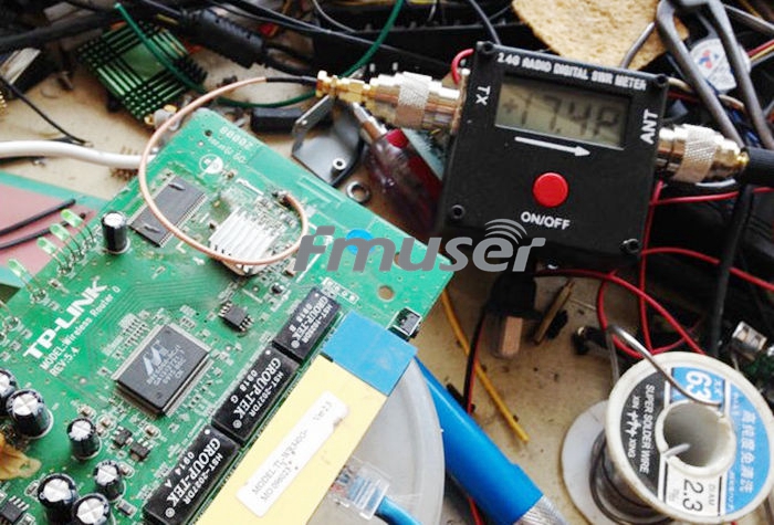
Internal view of FMUSER SWR bridge showing the PCB and coupler lines
See Also: >>What is VSWR and Return Loss?
Yet another method is to use torroidal pickups. These tend to have a much flatter response and enable the actual power levels to also be determined. The lines are frequency dependent.
You may also like: How To Calculate VSWR
How to Use a VSWR Meter
