
Products Category
- FM Transmitter
- 0-50w 50w-1000w 2kw-10kw 10kw+
- TV Transmitter
- 0-50w 50-1kw 2kw-10kw
- FM Antenna
- TV Antenna
- Antenna Accessory
- Cable Connector Power Splitter Dummy Load
- RF Transistor
- Power Supply
- Audio Equipments
- DTV Front End Equipment
- Link System
- STL system Microwave Link system
- FM Radio
- Power Meter
- Other Products
- Special for Coronavirus
Products Tags
Fmuser Sites
- es.fmuser.net
- it.fmuser.net
- fr.fmuser.net
- de.fmuser.net
- af.fmuser.net ->Afrikaans
- sq.fmuser.net ->Albanian
- ar.fmuser.net ->Arabic
- hy.fmuser.net ->Armenian
- az.fmuser.net ->Azerbaijani
- eu.fmuser.net ->Basque
- be.fmuser.net ->Belarusian
- bg.fmuser.net ->Bulgarian
- ca.fmuser.net ->Catalan
- zh-CN.fmuser.net ->Chinese (Simplified)
- zh-TW.fmuser.net ->Chinese (Traditional)
- hr.fmuser.net ->Croatian
- cs.fmuser.net ->Czech
- da.fmuser.net ->Danish
- nl.fmuser.net ->Dutch
- et.fmuser.net ->Estonian
- tl.fmuser.net ->Filipino
- fi.fmuser.net ->Finnish
- fr.fmuser.net ->French
- gl.fmuser.net ->Galician
- ka.fmuser.net ->Georgian
- de.fmuser.net ->German
- el.fmuser.net ->Greek
- ht.fmuser.net ->Haitian Creole
- iw.fmuser.net ->Hebrew
- hi.fmuser.net ->Hindi
- hu.fmuser.net ->Hungarian
- is.fmuser.net ->Icelandic
- id.fmuser.net ->Indonesian
- ga.fmuser.net ->Irish
- it.fmuser.net ->Italian
- ja.fmuser.net ->Japanese
- ko.fmuser.net ->Korean
- lv.fmuser.net ->Latvian
- lt.fmuser.net ->Lithuanian
- mk.fmuser.net ->Macedonian
- ms.fmuser.net ->Malay
- mt.fmuser.net ->Maltese
- no.fmuser.net ->Norwegian
- fa.fmuser.net ->Persian
- pl.fmuser.net ->Polish
- pt.fmuser.net ->Portuguese
- ro.fmuser.net ->Romanian
- ru.fmuser.net ->Russian
- sr.fmuser.net ->Serbian
- sk.fmuser.net ->Slovak
- sl.fmuser.net ->Slovenian
- es.fmuser.net ->Spanish
- sw.fmuser.net ->Swahili
- sv.fmuser.net ->Swedish
- th.fmuser.net ->Thai
- tr.fmuser.net ->Turkish
- uk.fmuser.net ->Ukrainian
- ur.fmuser.net ->Urdu
- vi.fmuser.net ->Vietnamese
- cy.fmuser.net ->Welsh
- yi.fmuser.net ->Yiddish
How to Use an SWR / VSWR Meter?

VSWR , Voltage Standing Wave Ratio / SWR meters are very useful, and although easy to use, there are a few useful hints and tips that can be applied.
Standing wave ratio meters come in a variety of forms, but essentially they are all used to measure the SWR, standing wave ratio on a transmitter feeder.
Understanding how to use a SWR meter is relatively easy, but sometimes knowing how to interpret the results and their limitations enables far more to be gained from using a VSWR meter.
There are many different SWR meters that are available, often aimed at the CB and amateur radio markets.
Some very low cost items are available, but sometimes it may be better to pay a little more and obtained a better quality instrument.
Note: VSWR meters and SWR meters are normally one and the same thing. Current and voltage standing waves are set up when power is reflected from a mismatch, and often their is a focus on the voltage elements.
Typical set-up for SWR meter
When looking at how to use a VSWR meter, most instructions are fairly vague, often just detailing which connector is to be connected to the antenna and which connector to the transmitter.
The basic set-up for a VSWR meter is as shown in the diagram below. The VSWR meter is connected in the feeder from the transmitter to the antenna. Typically it is located at the transmitter end of the feeder for convenience, and so that the actual VSWR as seen by the transmitter can be monitored.
The easiest way to achieve this is to connect the antenna plug normally connected to the transmitter into the VSWR meter socket labelled ANT or ANTENNA, and then use a short patch lead to connect the socket marked TX or TRANSMITTER on the VSWR meter to the transmitter.
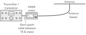
Very basic set-up for using a VSWR meter
See Also: How to Use a VSWR Meter
When an ATU or antenna matching and tuning unit is added to the set-up, the system shown below is normally used. By placing the VSWR meter between the transmitter and the ATU, the VSWR it sees is monitored. This is normally the most critical point to monitor the VSWR because high VSWR levels can damage the power amplifiers if no protection is incorporated, or it can result in the protection circuits backing off the power.
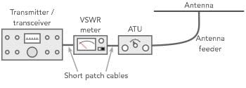
Incorporating an ATU into a transmitter feed system with a VSWR meter
How to use the SWR meter
Actually using the VSWR meter is very easy, but a few simple steps may help the first time user.
When using the VSWR meter to measure the performance of a new antenna or where the VSWR may not be know, it is wise to use a low power and a clear channel. With these concepts in mind the following procedure may be useful.
1)Find a clear channel or frequency:
It is worth listening for a short while in case you cannot hear one station in a two way contact
2)Reduce power:
Reduce the output power from the transmitter. This needs to be done in case there is a poor VSWR and it will reduce the likelihood of possible damage to the output devise of the transmitter.
3)Set mode switch:
Set the mode switch to a mode where a constant output is given, e.g. CW, AM or FM. In this way a steady reading is given. For CW (Morse) the key will need to be held down.
4)Set VSWR meter:
Srt the VSWR meter switch on the front panel to FORWARD, and turn the adjustment or CAL knob down - this prevents overloading the meter.
5)Adjust forward reading:
With the transmitter transmitting, adjust the knob on the CAL or adjustment knob so that a full scale reading is obtained.
6)Switch meter to reverse :
With the meter calibrated for the forward power, switch the meter to its reverse position and read the VSWR.
7)Stop transmitting :
It is good practice to stop transmitting as soon as possible. This reduces the possibility of interference to other stations and also reduces the overload on the transmitter output if the VSWR is poor.
8)Check on other frequencies:
If a wide band of frequencies or channels is to be used, then check the VSWR readings for the other frequencies or channels to be used because the VSWR will change over a range of frequencies.
Remember:
When transmitting on full power, it is often useful to leave the VSWR meter in circuit, but remember to calibrate it for the higher power output. Changes of power mean that the forward power needs to be reset using the CAL knob.
There is no general pass or fail mark when measuring VSWR. VSWR is measured as a ratio, i.e. 1:1 for no reflected power, 2:1, 3:1 and so forth. An open or a short circuit will be ∞:1.
Often VSWR meters will have a red calibration above 3:1 and this is probably the maximum you would want a transmitter to run with. A maximum of 2:1 would be better to prevent damage to the transmitter if it does not have protection on the output circuitry. Check the transmitter handbook in case there are guidelines on the maximum VSWR that the unit can work with.
But in reality there are no hard and fast rules. In general, the lower the better, but there will be very little difference in signal at the receiver between a VSWR of 1:1 and 2:1.
Where to measure SWR
It is important to know the best place to measure the VSWR for ease, seeing what VSWR is seen by the transmitter, and how the antenna is performing.
Unfortunately these requirements do not coincide and therefore it is necessary to understand what happens and how the VSWR measurements and readings can be distorted.
The main issue is the feeder loss that is always present to a greater or lesser degree. This can have a major effect on the VSWR readings that are seen.
Any feeder loss absorbs power in both directions, and a high level of feeder loss can mean that the reflected signal is much reduced. It is reduced as a forward signal to the antenna, and then again as a reflected signal back to the transmitter. This means that an antenna with a poor match and a very high VSWR may appear as being fine at the transmitter because the signal is reduced on its way to the antenna, and even thought he same percentage of power is reflected, it is the same percentage of a smaller amount. This means that with a feeder that introduces a high loss the VSWR can seem good at the transmitter, but at the antenna itself it may be very poor.

Diagram showing how feeder loss can improve the VSWR seen at the transmitter end of the feeder
See Also: VSWR(SWR) Calculation
The reflected power has been attenuated by 2 x 3dB, i.e. 6 dB and this means that a VSWR at the antenna of 8:1 is seen at the transmitter as a VSWR of 2.2:1 which is not bad.
In other words the high feeder loss makes it appear as if the antenna is functioning well.
Points to note when using a SWR meter: hints & tips
There are several points to note as well as some useful hints and tips when measuring VSWR.
1)Ensure meter connectors are correctly connected: Make sure that the ANT or ANTENNA connection is connected to the antenna, and the TX or TRANSMITTER connection links to the transmitter. The other way round and the forward and reverse positions on the switch will seem to be reversed.
2)Don’t operate into a high SWR: Be careful not to operate into a high SWR as damage can result to the transmitter, and occasionally the feeder.
Understanding how to use a VSWR meter is normally very easy. A few simple steps is all that is required to connect it and set it up. Once this has been done, then it can be left in circuit if needed.
