
Products Category
- FM Transmitter
- 0-50w 50w-1000w 2kw-10kw 10kw+
- TV Transmitter
- 0-50w 50-1kw 2kw-10kw
- FM Antenna
- TV Antenna
- Antenna Accessory
- Cable Connector Power Splitter Dummy Load
- RF Transistor
- Power Supply
- Audio Equipments
- DTV Front End Equipment
- Link System
- STL system Microwave Link system
- FM Radio
- Power Meter
- Other Products
- Special for Coronavirus
Products Tags
Fmuser Sites
- es.fmuser.net
- it.fmuser.net
- fr.fmuser.net
- de.fmuser.net
- af.fmuser.net ->Afrikaans
- sq.fmuser.net ->Albanian
- ar.fmuser.net ->Arabic
- hy.fmuser.net ->Armenian
- az.fmuser.net ->Azerbaijani
- eu.fmuser.net ->Basque
- be.fmuser.net ->Belarusian
- bg.fmuser.net ->Bulgarian
- ca.fmuser.net ->Catalan
- zh-CN.fmuser.net ->Chinese (Simplified)
- zh-TW.fmuser.net ->Chinese (Traditional)
- hr.fmuser.net ->Croatian
- cs.fmuser.net ->Czech
- da.fmuser.net ->Danish
- nl.fmuser.net ->Dutch
- et.fmuser.net ->Estonian
- tl.fmuser.net ->Filipino
- fi.fmuser.net ->Finnish
- fr.fmuser.net ->French
- gl.fmuser.net ->Galician
- ka.fmuser.net ->Georgian
- de.fmuser.net ->German
- el.fmuser.net ->Greek
- ht.fmuser.net ->Haitian Creole
- iw.fmuser.net ->Hebrew
- hi.fmuser.net ->Hindi
- hu.fmuser.net ->Hungarian
- is.fmuser.net ->Icelandic
- id.fmuser.net ->Indonesian
- ga.fmuser.net ->Irish
- it.fmuser.net ->Italian
- ja.fmuser.net ->Japanese
- ko.fmuser.net ->Korean
- lv.fmuser.net ->Latvian
- lt.fmuser.net ->Lithuanian
- mk.fmuser.net ->Macedonian
- ms.fmuser.net ->Malay
- mt.fmuser.net ->Maltese
- no.fmuser.net ->Norwegian
- fa.fmuser.net ->Persian
- pl.fmuser.net ->Polish
- pt.fmuser.net ->Portuguese
- ro.fmuser.net ->Romanian
- ru.fmuser.net ->Russian
- sr.fmuser.net ->Serbian
- sk.fmuser.net ->Slovak
- sl.fmuser.net ->Slovenian
- es.fmuser.net ->Spanish
- sw.fmuser.net ->Swahili
- sv.fmuser.net ->Swedish
- th.fmuser.net ->Thai
- tr.fmuser.net ->Turkish
- uk.fmuser.net ->Ukrainian
- ur.fmuser.net ->Urdu
- vi.fmuser.net ->Vietnamese
- cy.fmuser.net ->Welsh
- yi.fmuser.net ->Yiddish
What is VSWR?
Overview
VSWR (Known as Voltage Standing Wave Ratio), is a measure of how efficiently radio-frequency power is transmitted from a power source, through a transmission line, into a load (for example, from a power amplifier through a transmission line, to an antenna).
Standing waves are a key value for any system using transmission lines / feeders where measurements of the VSWR, Voltage Standing Wave Ratio are important.
Standing waves are an important issue when looking at feeders / transmission lines, and the standing wave ratio or more commonly the voltage standing wave ratio, VSWR is as a measurement of the level of standing waves on a feeder.

Standing waves represent power that is not accepted by the load and reflected back along the transmission line or feeder.
Although standing waves and VSWR are very important, often the VSWR theory and calculations can mask a view of what is actually happening. Fortunately, it is possible to gain a good view of the topic, without delving too deeply into VSWR theory.
Standing wave basics
When looking at systems that include transmission lines it is necessary to understand that sources, transmission lines / feeders and loads all have a characteristic impedance. 50Ω is a very common standard for RF applications although other impedances may occasionally be seen in some systems.
In order to obtain the maximum power transfer from the source to the transmission line, or the transmission line to the load, be it a resistor, an input to another system, or an antenna, the impedance levels must match.
In other words for a 50Ω system the source or signal generator must have a source impedance of 50Ω, the transmission line must be 50Ω and so must the load.

Matched feeder and load are required for maximum power transfer
As power cannot disappear, the power that is not transferred into the load has to go somewhere and there it travels back along the transmission line back towards the source.

See Also: Why Do I Need a Transmitter Circuit before An Antenna?
When this happens the voltages and currents of the forward and reflected waves in the feeder add or subtract at different points along the feeder according to the phases. In this way standing waves are set up.
The way in which the effect occurs can be demonstrated with a length of rope. If one end is left free and the other is moved up an down the wave motion can be seen to move down along the rope. However if one end is fixed a standing wave motion is set up, and points of minimum and maximum vibration can be seen.
When the load resistance is lower than the feeder impedance voltage and current magnitudes are set up. Here the total current at the load point is higher than that of the perfectly matched line, whereas the voltage is less.

Voltage and current standing wave patterns for small impedance mismatch with load lower than feeder impedance
See Also: VSWR Calculating Tools

Voltage and current standing wave patterns for short circuit feeder termination
See Also: Understanding Reflections and Standing Waves in RF Circuit Design
A similar situation occurs when the load resistance is greater than the feeder impedance however this time the total voltage at the load is higher than the value of the perfectly matched line. The voltage reaches a minimum at a distance a quarter of a wavelength from the load and the current is at a maximum. However at a distance of a half wavelength from the load the voltage and current are the same as at the load.

Voltage and current standing wave patterns for small impedance mismatch with load higher than the feeder impedance
See Also: VSWR(SWR) Calculation

See Also: Make this Radio Repeater Circuit at Home
VSWR definition
The definition of VSWR provides the basis for all the calculations and formulas.
VSWR definition:
The voltage standing wave ratio, VSWR is defined as the ratio of the maximum to minimum voltage on a loss-less line.
The resulting ratio is normally expressed as a ratio, e.g. 2:1, 5:1, etc. A perfect match is 1:1 and a complete mismatch, i.e. a short or open circuit is ∞:1.
In practice there is a loss on any feeder or transmission line. To measure the VSWR, forward and reverse power is detected at that point on the system and this is converted to a figure for VSWR. In this way, the VSWR is measured at a particular point and the voltage maxima and minima do not need to be determined along the length of the line.
VSWR vs SWR
The terms VSWR and SWR are often seen in the literature about standing waves in RF systems, and many ask about the difference.
SWR: SWR stands for standing wave ratio. It describes the voltage and current standing waves that appear on the line. It is a generic description for both current and voltage standing waves. It is often used in association with meters used to detect the standing wave ratio. Both current and voltage rise and fall by the same proportion for a given mismatch.
VSWR: The VSWR or voltage standing wave ratio applies specifically to the voltage standing waves that are set up on a feeder or transmission line. As it is easier to detect the voltage standing waves, and in many instances voltages are more important in terms of device breakdown, the term VSWR is often used, especially within RF design areas.
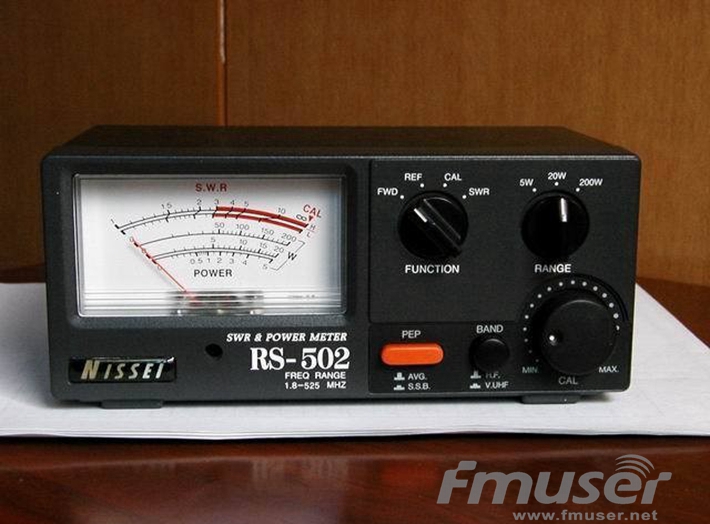
Typical VSWR meter used with a transmitter
There are several ways in which VSWR affects the performance of a transmitter system, or any system that may use RF and matched impedances.
Although the term VSWR is normally used, both the voltage and current standing waves can cause issues. Some of the affects are detailed below:
Transmitter power amplifiers can be damaged: The increased levels of voltage and current seen on the feeder as a result of the standing waves, can damage the output transistors of the transmitter. Semiconductor devices are very reliable if operated within their specified limits, but the voltage and current standing waves on the feeder can cause catastrophic damage if they cause the devise to operate outside their limits.
PA Protection reduces output power: In view of the very real danger of high SWR levels causing damage to the power amplifier, many transmitters incorporate protection circuitry which reduces the output from the transmitter as the SWR rises. This means that a poor match between the feeder and antenna will result in a high SWR which causes the output to be reduced and hence a significant loss in transmitted power.
High voltage and current levels can damage feeder: It is possible that the high voltage and current levels caused by the high standing wave ratio can cause damage to a feeder. Although in most cases feeders will be operated well within their limits and the doubling of voltage and current should be able to be accommodated, there are some circumstances when damage can be caused. The current maxima can cause excessive local heating which could distort or melt the plastics used, and the high voltages have been known to cause arcing in some circumstances.
Delays caused by reflections can cause distortion: When a signal is reflected by mismatch, it is reflected back towards the source, and can then be reflected back again towards the antenna. A delay is introduced equal to twice the transmission time of the signal along the feeder. If data is being transmitted this can cause inter-symbol interference, and in another example where analogue television was being transmitted, a “ghost” image was seen.
Reduction in signal compared to perfectly match system: Interestingly the loss in signal level caused by a poor VSWR is not nearly as great as some may imagine. Any signal reflected by the load, is reflected back to the transmitter and as matching at the transmitter can enable the signal to be reflected back to the antenna again, the losses incurred are fundamentally those introduced by the feeder. As a guide a 30 metre length of coax with a loss of around 1.5 dB at 30 MHz will mean that an antenna operating with a VSWR will only give a loss of just over 1dB at this frequency compared to a perfectly matched antenna.
Standing wave ratio is an important parameter for any feeder system. Although both current and voltage standing waves are set up, it is often the voltage standing wave ratio that is more widely discussed, as a result of the fact it is easier to detect and measure.
You may also like: How To Calculate VSWR
What is VSWR and Return Loss?
How to Use a VSWR Meter
