
Products Category
- FM Transmitter
- 0-50w 50w-1000w 2kw-10kw 10kw+
- TV Transmitter
- 0-50w 50-1kw 2kw-10kw
- FM Antenna
- TV Antenna
- Antenna Accessory
- Cable Connector Power Splitter Dummy Load
- RF Transistor
- Power Supply
- Audio Equipments
- DTV Front End Equipment
- Link System
- STL system Microwave Link system
- FM Radio
- Power Meter
- Other Products
- Special for Coronavirus
Products Tags
Fmuser Sites
- es.fmuser.net
- it.fmuser.net
- fr.fmuser.net
- de.fmuser.net
- af.fmuser.net ->Afrikaans
- sq.fmuser.net ->Albanian
- ar.fmuser.net ->Arabic
- hy.fmuser.net ->Armenian
- az.fmuser.net ->Azerbaijani
- eu.fmuser.net ->Basque
- be.fmuser.net ->Belarusian
- bg.fmuser.net ->Bulgarian
- ca.fmuser.net ->Catalan
- zh-CN.fmuser.net ->Chinese (Simplified)
- zh-TW.fmuser.net ->Chinese (Traditional)
- hr.fmuser.net ->Croatian
- cs.fmuser.net ->Czech
- da.fmuser.net ->Danish
- nl.fmuser.net ->Dutch
- et.fmuser.net ->Estonian
- tl.fmuser.net ->Filipino
- fi.fmuser.net ->Finnish
- fr.fmuser.net ->French
- gl.fmuser.net ->Galician
- ka.fmuser.net ->Georgian
- de.fmuser.net ->German
- el.fmuser.net ->Greek
- ht.fmuser.net ->Haitian Creole
- iw.fmuser.net ->Hebrew
- hi.fmuser.net ->Hindi
- hu.fmuser.net ->Hungarian
- is.fmuser.net ->Icelandic
- id.fmuser.net ->Indonesian
- ga.fmuser.net ->Irish
- it.fmuser.net ->Italian
- ja.fmuser.net ->Japanese
- ko.fmuser.net ->Korean
- lv.fmuser.net ->Latvian
- lt.fmuser.net ->Lithuanian
- mk.fmuser.net ->Macedonian
- ms.fmuser.net ->Malay
- mt.fmuser.net ->Maltese
- no.fmuser.net ->Norwegian
- fa.fmuser.net ->Persian
- pl.fmuser.net ->Polish
- pt.fmuser.net ->Portuguese
- ro.fmuser.net ->Romanian
- ru.fmuser.net ->Russian
- sr.fmuser.net ->Serbian
- sk.fmuser.net ->Slovak
- sl.fmuser.net ->Slovenian
- es.fmuser.net ->Spanish
- sw.fmuser.net ->Swahili
- sv.fmuser.net ->Swedish
- th.fmuser.net ->Thai
- tr.fmuser.net ->Turkish
- uk.fmuser.net ->Ukrainian
- ur.fmuser.net ->Urdu
- vi.fmuser.net ->Vietnamese
- cy.fmuser.net ->Welsh
- yi.fmuser.net ->Yiddish
Wilkinson Power Divider Splitter Combiner
Wilkinson Power Divider Splitter Combiner
- overview and essentials of the Wilkinson divider splitter combiner - how it works, design criteria, and formulae.The Wilkinson divider splitter / Wilkinson combiner is a form of power splitter / power combiner that is often used in microwave applications. It uses quarter wave transformers, which are easily fabricated as quarter wave lines on printed circuit boards and as a result it offers the possibility of proving a very cheap and simple splitter / divider / combiner while still providing high levels of performance. While the printed circuit board transmission line approach is widely used for the Wilkinson divider / splitter combiner, it is also possible to use other forms of transmission line (e.g. coaxial cable) or lumped circuit elements (inductors and capacitors).
The Wilkinson power divider or Wilkinson splitter as it is also known takes its name from Ernest Wilkinson, the electronics engineer who initially developed it in the 1960s. Wilkinson published his idea in IRE Trans. on Microwave Theory and Techniques, in January 1960 under the title: "An N-way Power Divider".
Wilkinson power divider splitter combiner advantages and disadvantages
In order to determine whether to use a Wilkinson power divider splitter / Wilkinson combiner, it is necessary to weigh up the advantages and disadvantages of using them.
-Simplicity: The Wilkinson divider / splitter / combiner is particularly simple and can easily be realised using printed components on a printed circuit board. It is also possible to use lumped inductor and capacitor elements, but this complicates the overall design.
-Cost: When the Wilkinson power divider is realised using printed circuit board elements, the cost is very low - possibly the only increase above that of the single resistor used results from an increase in the board area used as a result of the printed elements. However to reduce losses, a low loss PCB substrate may need to be used and this would increase the cost.
-Loss: If perfect components were used, the Wilkinson splitter divider would not introduce any additional loss above that arising from the division of the power between the different ports. In addition to this, the real components used for the Wilkinson splitter can be very low loss, especially when PCB transmission lines are used along with low loss PCB substrate material.
-isolation: The Wilkinson divider / combiner provides a high degree of isolation between the "output" ports.
-Frequency response: As the Wilkinson splitter is based around the use of quarter wave transmission lines, it has a limited bandwidth, although there are some Wilkinson splitters available that offer reasonably wide bandwidths.
2 way Wilkinson power divider basics
Although the Wilkinson power divider concept can be used for an N-way system, it is easiest to see how it operates as a two way system, and later expand it out to see how the Wilkinson power splitter can be used as an n-way device.
The Wilkinson power divider / Wilkinson combiner uses quarter wave transformers to split the input signal to provide two output signals that are in phase with each other.
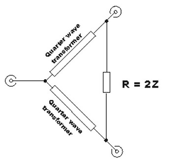
A two way Wilkinson power splitter / divider and Wilkinson combiner
The values within the two way Wilkinson divider / combiner can be calculated:
R = the value of the terminating resistor connected between the two ports
Zo = the characteristic impedance of the overall system
Zmatch = the impedance of the quarter wave transformers in the legs of the power divider combiner.
In order to see how the Wilkinson divider works, consider a signal entering the left hand port, port 1 in the diagram above. The signal reaches the physical split and passes to both outputs, ports two and three of the Wilkinson divider. As the two legs of splitter / divider are identical, the signals appearing at the outputs will have the same phase. This means that ports 2 and 3 will be at the same potential and no current will flow in the resistor.
As the power is being split, it is necessary to ensure that the impedances within the Wilkinson divider are maintained. To achieve this, the two output ports must each appear as an impedance of 2 x Zo - the two output ports of 2 Zo in parallel will present an overall impedance of Zo. The impedance transformation is achieved by placing a quarter wave transmission line between the star point and the output - the transmission line has an impedance of 1.414 x Zo. In this way, the impedance within the system is maintained.
