
Products Category
- FM Transmitter
- 0-50w 50w-1000w 2kw-10kw 10kw+
- TV Transmitter
- 0-50w 50-1kw 2kw-10kw
- FM Antenna
- TV Antenna
- Antenna Accessory
- Cable Connector Power Splitter Dummy Load
- RF Transistor
- Power Supply
- Audio Equipments
- DTV Front End Equipment
- Link System
- STL system Microwave Link system
- FM Radio
- Power Meter
- Other Products
- Special for Coronavirus
Products Tags
Fmuser Sites
- es.fmuser.net
- it.fmuser.net
- fr.fmuser.net
- de.fmuser.net
- af.fmuser.net ->Afrikaans
- sq.fmuser.net ->Albanian
- ar.fmuser.net ->Arabic
- hy.fmuser.net ->Armenian
- az.fmuser.net ->Azerbaijani
- eu.fmuser.net ->Basque
- be.fmuser.net ->Belarusian
- bg.fmuser.net ->Bulgarian
- ca.fmuser.net ->Catalan
- zh-CN.fmuser.net ->Chinese (Simplified)
- zh-TW.fmuser.net ->Chinese (Traditional)
- hr.fmuser.net ->Croatian
- cs.fmuser.net ->Czech
- da.fmuser.net ->Danish
- nl.fmuser.net ->Dutch
- et.fmuser.net ->Estonian
- tl.fmuser.net ->Filipino
- fi.fmuser.net ->Finnish
- fr.fmuser.net ->French
- gl.fmuser.net ->Galician
- ka.fmuser.net ->Georgian
- de.fmuser.net ->German
- el.fmuser.net ->Greek
- ht.fmuser.net ->Haitian Creole
- iw.fmuser.net ->Hebrew
- hi.fmuser.net ->Hindi
- hu.fmuser.net ->Hungarian
- is.fmuser.net ->Icelandic
- id.fmuser.net ->Indonesian
- ga.fmuser.net ->Irish
- it.fmuser.net ->Italian
- ja.fmuser.net ->Japanese
- ko.fmuser.net ->Korean
- lv.fmuser.net ->Latvian
- lt.fmuser.net ->Lithuanian
- mk.fmuser.net ->Macedonian
- ms.fmuser.net ->Malay
- mt.fmuser.net ->Maltese
- no.fmuser.net ->Norwegian
- fa.fmuser.net ->Persian
- pl.fmuser.net ->Polish
- pt.fmuser.net ->Portuguese
- ro.fmuser.net ->Romanian
- ru.fmuser.net ->Russian
- sr.fmuser.net ->Serbian
- sk.fmuser.net ->Slovak
- sl.fmuser.net ->Slovenian
- es.fmuser.net ->Spanish
- sw.fmuser.net ->Swahili
- sv.fmuser.net ->Swedish
- th.fmuser.net ->Thai
- tr.fmuser.net ->Turkish
- uk.fmuser.net ->Ukrainian
- ur.fmuser.net ->Urdu
- vi.fmuser.net ->Vietnamese
- cy.fmuser.net ->Welsh
- yi.fmuser.net ->Yiddish
Resistive splitter / divider combiner
Resistive splitter / divider combiner
- and introduction to resistor based or resistive RF combiners, and splitters or dividers, detailing formulae, circuits and other essential details
The easiest way of making an RF splitter or RF combiner is to utilise simple resistive elements. The use of resistors in a resistive combiner or resistive splitter enables the characteristic impedance of the system to be maintained while allowing the signal to be split or combined.
As the name implies, RF resistive splitters and resistive combiners utilise resistors as the main element to enable the splitting or combining action to take place.
Resistive splitter combiner advantages and disadvantages
As may be imagined, resistive splitters and resistive combiners have a number of advantages and disadvantages. These need to be considered when deciding what form of splitter / combiner to use or design into some equipment.
-Advantages
*Simplicity: A resistive splitter / combiner is particularly simple, being made up from only resistors. They can be made very easily within a circuit requiring little design and preparation.
*Cost: Being made from only resistors, the cost of a resistive combiner / splitter is very low.
*Frequency response: Provided that suitable resistors and construction techniques are used, the frequency response can extend over a wide frequency range.
-Disadvantages
*Loss: Using resistors, power is lost over an above the reduction in power level resulting from the division of the power between several outputs in a splitter.
Resistive splitter divider basics
There is a large variety of different types of resistive divider or splitter. They can be used to provide an RF split or division in any ratio, simply by choosing the correct values of resistor and configuration. They are also able to provide an accurate impedance match over a wide band of frequencies provided the correct types of resistor and construction techniques are used.
A variety of different configurations can be used for RF resistive power splitters / RF resistive power dividers.
6 dB three way resistive power divider / splitter
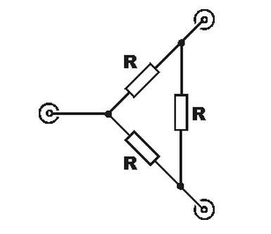
One of the most commonly seen forms of resistive power divider or power splitter is the simple three way resistive splitter or divider. There are two configurations that can be seen - namely star or delta configurations.
-Star format power splitter divider: The star format for the power divider splitter is possibly the more widely used of the two formats.
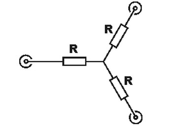
In the star example, the series resistors to the star point are all equal and have a resistance that has a value:
It is necessary to remember that power is dissipated in these resistors and that their power rating must be sufficient to dissipate the expected levels of power (with some margin).
In this example the resistance of the resistors is equal to that of the characteristic impedance of the RF system.
With these simple forms of resistive power divider or splitter, any port can be used as the input, the remaining ones being used as the outputs. The outputs are 6 dB down on the input level, 3 dB of additional losses are incurred over the level reduction of 3 dB that would be experienced if an ideal transformer based "hybrid" splitter was used that incurred no dissipative losses.
N-1 way power divider, splitter, combiner
It is possible to make resistive power dividers that have any number of ports. Power reductions will obviously be greater, but in many instances it will be possible to tolerate these increased losses. The most straightforward design is based upon the star power divider configuration. It is achieved by simply linking more resistors and ports to the star point.
For any number of outputs, there will be N ports - the additional port being required for the input.
