Products Category
- FM Transmitter
- 0-50w 50w-1000w 2kw-10kw 10kw+
- TV Transmitter
- 0-50w 50-1kw 2kw-10kw
- FM Antenna
- TV Antenna
- Antenna Accessory
- Cable Connector Power Splitter Dummy Load
- RF Transistor
- Power Supply
- Audio Equipments
- DTV Front End Equipment
- Link System
- STL system Microwave Link system
- FM Radio
- Power Meter
- Other Products
- Special for Coronavirus
Products Tags
Fmuser Sites
- es.fmuser.net
- it.fmuser.net
- fr.fmuser.net
- de.fmuser.net
- af.fmuser.net ->Afrikaans
- sq.fmuser.net ->Albanian
- ar.fmuser.net ->Arabic
- hy.fmuser.net ->Armenian
- az.fmuser.net ->Azerbaijani
- eu.fmuser.net ->Basque
- be.fmuser.net ->Belarusian
- bg.fmuser.net ->Bulgarian
- ca.fmuser.net ->Catalan
- zh-CN.fmuser.net ->Chinese (Simplified)
- zh-TW.fmuser.net ->Chinese (Traditional)
- hr.fmuser.net ->Croatian
- cs.fmuser.net ->Czech
- da.fmuser.net ->Danish
- nl.fmuser.net ->Dutch
- et.fmuser.net ->Estonian
- tl.fmuser.net ->Filipino
- fi.fmuser.net ->Finnish
- fr.fmuser.net ->French
- gl.fmuser.net ->Galician
- ka.fmuser.net ->Georgian
- de.fmuser.net ->German
- el.fmuser.net ->Greek
- ht.fmuser.net ->Haitian Creole
- iw.fmuser.net ->Hebrew
- hi.fmuser.net ->Hindi
- hu.fmuser.net ->Hungarian
- is.fmuser.net ->Icelandic
- id.fmuser.net ->Indonesian
- ga.fmuser.net ->Irish
- it.fmuser.net ->Italian
- ja.fmuser.net ->Japanese
- ko.fmuser.net ->Korean
- lv.fmuser.net ->Latvian
- lt.fmuser.net ->Lithuanian
- mk.fmuser.net ->Macedonian
- ms.fmuser.net ->Malay
- mt.fmuser.net ->Maltese
- no.fmuser.net ->Norwegian
- fa.fmuser.net ->Persian
- pl.fmuser.net ->Polish
- pt.fmuser.net ->Portuguese
- ro.fmuser.net ->Romanian
- ru.fmuser.net ->Russian
- sr.fmuser.net ->Serbian
- sk.fmuser.net ->Slovak
- sl.fmuser.net ->Slovenian
- es.fmuser.net ->Spanish
- sw.fmuser.net ->Swahili
- sv.fmuser.net ->Swedish
- th.fmuser.net ->Thai
- tr.fmuser.net ->Turkish
- uk.fmuser.net ->Ukrainian
- ur.fmuser.net ->Urdu
- vi.fmuser.net ->Vietnamese
- cy.fmuser.net ->Welsh
- yi.fmuser.net ->Yiddish
4 Simple FM Transmitter Circuits Explained
An FM transmitter circuit is a high frequency wireless device which is able to transmit voice signals into atmosphere so that it can be received by a corresponding FM receiver circuit for reproducing the voice signals in a loudspeaker.Here we’ll discuss how to build small FM transmitter circuits using 4 different methods.All the FM transmitter circuits presented below are significantly powerful, hard to trace in their hidden positions, and equipped for grasping even the weakest of whispers in the vicinity. Moreover the designs are capable of transmitting the picked information upto radial distances exceeding 2 kms.
Using Tuned Circuit
The first example below shows a single transistor FM spy circuit that incorporates a tuned circuit or a frequency determining stage in it.In the original prototype the coil was created by etching a spiral track layout on the PCB itself, however for optimal gain and performance such etched antenna coil must be avoided and the traditional wire wound type of coil must be employed.
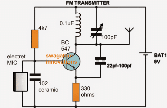
Incorporating Q Factor
Below's another circuit you would like to know about. The circuit basically makes use of the “Q factor” of the tank network achieved from the coil and the capacitor for generating a relatively high voltage. This stepped up potential attributes the circuit with a rather longer range of transmission.
For an improved performance make sure the coil and the capacitor are positioned as close as possible. Insert the coil leads as deep down the PCB as possible in order to make it tightly hugging the PCB. C2 value could be tweaked for achieving even better response from the circuit.
Preferably a 10pF could be tried. The coil is made of 5 turns of 1mm thick super enamelled copper wire, with 7mm diameter.
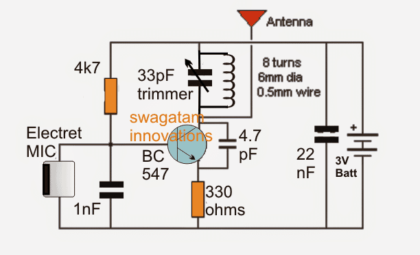
The next FM transmitter design is a bit different than the above types. Fundamentally the design could be classified as a common emitter type, unlike the others which are rather common base types with their design.
The circuit employs an inductor at its base which adds a better saturation capability to the device which in turn allows the transistor to respond in a much healthier way.
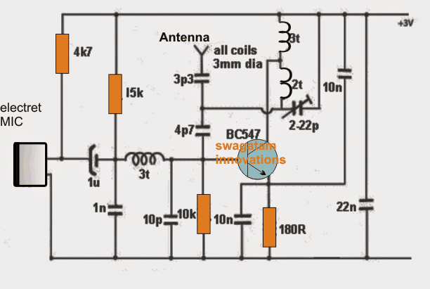
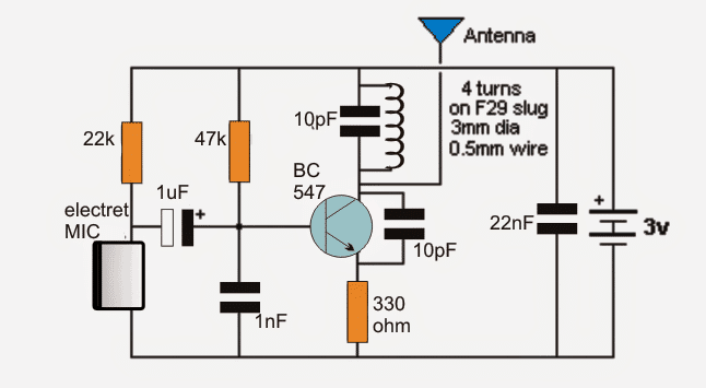
The next design in the list is much superior to its previous counterparts since it uses a slug based variable inductor.
This enables the transmitter to be tuned by adjusting the slug core using a screwdriver. In this configuration we can see the coil being attached to the collector of the transistor which allows a massive 200 meters range to the design, with a current that may be not more than 5mA.
The MIC stage is isolated from the base with the help of a 1u capacitor and the gain of the mic could be well tweaked by adjusting the series 22k resistor.
This circuit could be rated as the best as far range is concerned however it may lack stability which could be improved, we’ll learn how in the following explanation.