
Products Category
- FM Transmitter
- 0-50w 50w-1000w 2kw-10kw 10kw+
- TV Transmitter
- 0-50w 50-1kw 2kw-10kw
- FM Antenna
- TV Antenna
- Antenna Accessory
- Cable Connector Power Splitter Dummy Load
- RF Transistor
- Power Supply
- Audio Equipments
- DTV Front End Equipment
- Link System
- STL system Microwave Link system
- FM Radio
- Power Meter
- Other Products
- Special for Coronavirus
Products Tags
Fmuser Sites
- es.fmuser.net
- it.fmuser.net
- fr.fmuser.net
- de.fmuser.net
- af.fmuser.net ->Afrikaans
- sq.fmuser.net ->Albanian
- ar.fmuser.net ->Arabic
- hy.fmuser.net ->Armenian
- az.fmuser.net ->Azerbaijani
- eu.fmuser.net ->Basque
- be.fmuser.net ->Belarusian
- bg.fmuser.net ->Bulgarian
- ca.fmuser.net ->Catalan
- zh-CN.fmuser.net ->Chinese (Simplified)
- zh-TW.fmuser.net ->Chinese (Traditional)
- hr.fmuser.net ->Croatian
- cs.fmuser.net ->Czech
- da.fmuser.net ->Danish
- nl.fmuser.net ->Dutch
- et.fmuser.net ->Estonian
- tl.fmuser.net ->Filipino
- fi.fmuser.net ->Finnish
- fr.fmuser.net ->French
- gl.fmuser.net ->Galician
- ka.fmuser.net ->Georgian
- de.fmuser.net ->German
- el.fmuser.net ->Greek
- ht.fmuser.net ->Haitian Creole
- iw.fmuser.net ->Hebrew
- hi.fmuser.net ->Hindi
- hu.fmuser.net ->Hungarian
- is.fmuser.net ->Icelandic
- id.fmuser.net ->Indonesian
- ga.fmuser.net ->Irish
- it.fmuser.net ->Italian
- ja.fmuser.net ->Japanese
- ko.fmuser.net ->Korean
- lv.fmuser.net ->Latvian
- lt.fmuser.net ->Lithuanian
- mk.fmuser.net ->Macedonian
- ms.fmuser.net ->Malay
- mt.fmuser.net ->Maltese
- no.fmuser.net ->Norwegian
- fa.fmuser.net ->Persian
- pl.fmuser.net ->Polish
- pt.fmuser.net ->Portuguese
- ro.fmuser.net ->Romanian
- ru.fmuser.net ->Russian
- sr.fmuser.net ->Serbian
- sk.fmuser.net ->Slovak
- sl.fmuser.net ->Slovenian
- es.fmuser.net ->Spanish
- sw.fmuser.net ->Swahili
- sv.fmuser.net ->Swedish
- th.fmuser.net ->Thai
- tr.fmuser.net ->Turkish
- uk.fmuser.net ->Ukrainian
- ur.fmuser.net ->Urdu
- vi.fmuser.net ->Vietnamese
- cy.fmuser.net ->Welsh
- yi.fmuser.net ->Yiddish
A Complete Guide to VSWR from FMUSER [Updated 2022]
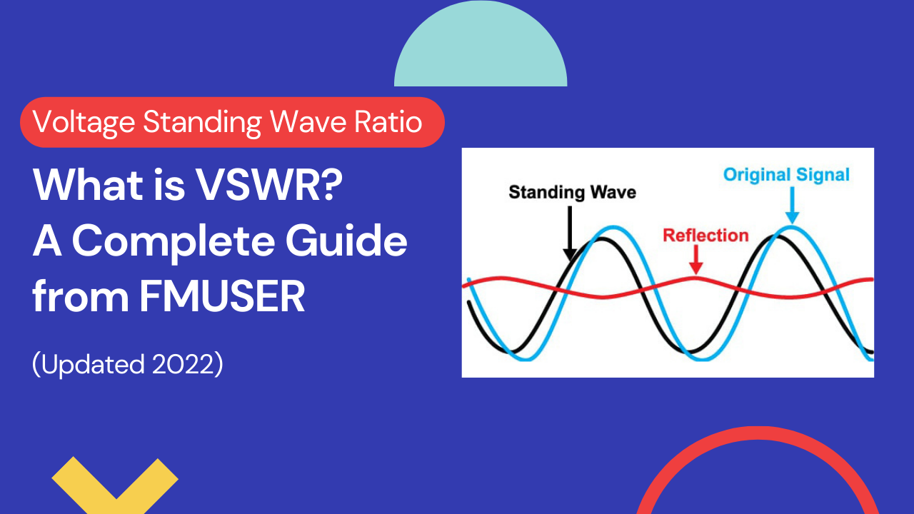
In antenna theory, VSWR is abbreviated from voltage standing wave ratio.
VSWR is a measurement of the standing wave level on a feeder line, it is also known as standing wave ratio (SWR).
We know that the standing wave, which explains the standing wave ratio, is such an important factor to be considered for engineers when conducting RF technical research on antennas.
Although standing waves and VSWR are very important, often the VSWR theory and calculations can mask a view of what is actually happening. Fortunately, it is possible to gain a good view of the topic, without delving too deeply into VSWR theory.
But what actually is VSWR and what does it mean for broadcasting? This blog is the most complete guide about VSWR, including what it is, how it works, and everything you need to know about VSWR.
Let's keep exploring!
Sharing is caring!
1. What is VSWR? Voltage Standing Wave Ratio Basics
1) About VSWR
-VSWR Defintion
What is VSWR? Simply putting, VSWR is defined as the ratio between transmitted and reflected voltage standing waves in a radio frequency (RF) electrical transmission system.
-Abbreviation of VSWR
VSWR is abbreviated from voltage standing wave ratio, it is sometimes pronounced as "viswar".
-How VSWR Works
VSWR is considered as a measurment of how efficiently RF power is transmitted - from the power source and then goes through a transmission line, and finally goes into the load.
-VSWR in Broadcasting
VSWR is used as an efficiency measure for everything conveying RF includes transmission lines, electrical cables, and even the signal in the air. A common example is a power amplifier connected to an antenna through a transmission line. That's why you may also considered VSWR as the ratio of the maximum to minimum voltage on a loss-less line.
2) What are the Main Functions of VSWR?
VSWR are widely used in a variety of applications, such as in antenna, telecom, microwave, radio frequency (RF), etc.
Here are some of the main applications with explanation:
| Applications of VSWR | Main functions of VSWR |
|
Transmitting Antenna |
The Voltage Standing Wave Ratio (VSWR) is an indication of the amount of mismatch between an antenna and the feed line connecting to it. This is also known as the Standing Wave Ratio (SWR). The range of values for VSWR is from 1 to ∞ . A VSWR value under 2 is considered suitable for most antenna applications. The antenna can be described as having a “Good Match”. So when someone says that the antenna is poorly matched, very often it means that the VSWR value exceeds 2 for a frequency of interest. |
| Telecommunication |
In telecommunications, the standing wave ratio (SWR) is the ratio of the amplitude of a partial standing wave at an antinode (maximum) to the amplitude at an adjacent node (minimum) in an electrical transmission line. |
|
Microwave |
Common performance measures associated with microwave transmission lines and circuits are VSWR, reflection coefficient and return loss, as well as transmission coefficient and insertion loss. These may all be expressed using scattering parameters, more commonly referred to a S-parameters. |
| RF |
Voltage standing wave ratio (VSWR) is defined as the ratio between transmitted and reflected voltage standing waves in a radio frequency (RF) electrical transmission system. It is a measure of how efficiently RF power is transmitted from the power source, through a transmission line, and into the load |
3) Learn How to Express VSWR from Technician Jimmy
Here is a basic simplified RF knowledge list provided by our RF technician Jimmy. Let's learn more about VSWR through the following content:
- Expressing VSWR Using Voltage
By the definition, VSWR is the ratio of the highest voltage (the maximum amplitude of the standing wave) to the lowest voltage (the minimum amplitude of the standing wave) anywhere between source and load.
VSWR = |V(max)| / |V(min)|
V(max) = the maximum amplitude of the standing wave
V(min) = the minimum amplitude of the standing wave
- Expressing VSWR Using an Impedance
By the definition, VSWR is the ratio of the load impedance and source impedance.
VSWR = ZL/Zo
ZL = the load impedance
Zo = the source impedance
What is the Ideal Value of a VSWR?
The value of an ideal VSWR is 1:1 or shortly expressed as 1. In this case the reflected power from the load to the source is zero.
- Expressing VSWR Using Reflection and Forward Power
By the definition VSWR is equal to
VSWR = 1 + √(Pr/Pf) / 1 – √(Pr/Pf)
where:
Pr = Reflected power
Pf = Forward power
3) Why Should I Care VSWR? Why it Matters?
The definition of VSWR provides the basis for all the VSWR calculations and formulas.
In a connected line, an impedance mismatch can cause reflection, which is just what it sounds like— a wave bouncing back and going the wrong direction.
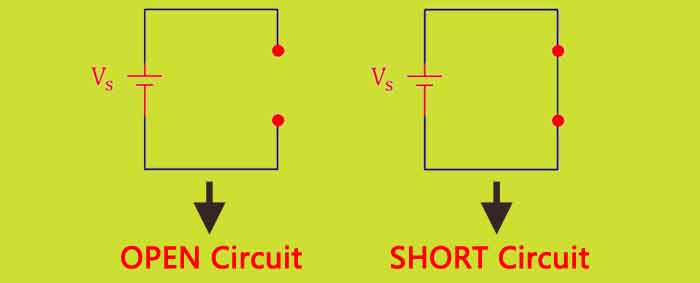
Main reason: All the energy gets reflected (for example, by an open or short circuit) at the end of the line, then none gets absorbed, producing a perfect "standing wave" on the line.
The result of the opposing waves is a standing wave. This diminishes the power the antenna receives and can use to broadcast. It can even burn out a transmitter.
The value of VSWR presents the power reflected from the load to the source. It is often used to describe how much power is lost from the source (usually a High Frequency Amplifier) through a transmission line (usually a coaxial cable) to the load (usually an antenna).
This is a bad situation: Your transmitter burns down due to over-hight energy.
In fact, when the power meant to be radiated comes back into the transmitter at full strength, it will usually burn out the electronics there.
It is hard to understand? Here is an example that might help you:
An ocean wavetrain traveling toward shore carries energy toward the beach. If it runs up onto a gently sloping beach, all of the energy gets absorbed, and there are no waves traveling back offshore.
If instead of a sloping beach a vertical seawall is present, then the incoming wavetrain gets completely reflected, so that no energy is absorbed in the wall.
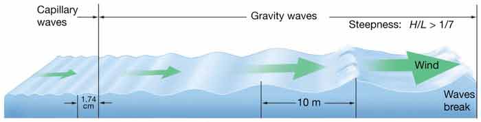
The interference between the incoming and outgoing waves in this case produces a "standing wave" that doesn't look like it is traveling at all; the peaks stay in the same spatial positions and just go up and down.
The same phenomenon happens on a radio or radar transmission line.
In this case, we want the waves on the line (both voltage and current) to travel one way and deposit their energy into the desired load, which in this case may be an antenna where it is to be radiated.
If all the energy gets reflected (for example, by an open or short circuit) at the end of the line, then none gets absorbed, producing a perfect "standing wave" on the line.
It doesn't take an open or short circuit to cause a reflected wave. All it takes is a mismatch in impedance between the line and the load.
If the reflected wave is not as strong as the forward wave, then some "standing wave" pattern will be observed, but the nulls will not be as deep nor the peaks as high as for a perfect reflection (or complete mismatch).
2. What is SWR?
1) SWR Definition
According to Wikipedia, standing wave ratio (SWR) defined as:
‘’A measure of impedance matching of loads to the characteristic impedance of a transmission line or waveguide in radio engineering and telecommunications. SWR is, thus, the ratio between transmitted and reflected waves or the ratio between the amplitude of a standing wave at it's maximum, to the amplitude at the minimum, SWR is usually defined as a voltage ratio called the VSWR”.
A high SWR indicates poor transmission-line efficiency and reflected energy, which can damage the transmitter and decrease transmitter efficiency.
Since SWR commonly refers to the voltage ratio, it is usually known as the voltage standing wave ratio (VSWR).
2) How VSWR Affects the Performance of a Transmitter System?
There are several ways in which VSWR affects the performance of a transmitter system, or any system that may use RF and matched impedances.
Although the term VSWR is normally used, both the voltage and current standing waves can cause issues. Some of the affects are detailed below:
-Transmitter Power Amplifiers Can be Damaged
The increased levels of voltage and current seen on the feeder as a result of the standing waves, can damage the output transistors of the transmitter. Semiconductor devices are very reliable if operated within their specified limits, but the voltage and current standing waves on the feeder can cause catastrophic damage if they cause the devise to operate outside their limits.
-PA Protection Reduces Output Power
In view of the very real danger of high SWR levels causing damage to the power amplifier, many transmitters incorporate protection circuitry which reduces the output from the transmitter as the SWR rises. This means that a poor match between the feeder and antenna will result in a high SWR which causes the output to be reduced and hence a significant loss in transmitted power.
-High Voltage and Current Levels can Damage Feeder
It is possible that the high voltage and current levels caused by the high standing wave ratio can cause damage to a feeder. Although in most cases feeders will be operated well within their limits and the doubling of voltage and current should be able to be accommodated, there are some circumstances when damage can be caused. The current maxima can cause excessive local heating which could distort or melt the plastics used, and the high voltages have been known to cause arcing in some circumstances.
-Delays Caused by Reflections can Cause Distortion:
When a signal is reflected by mismatch, it is reflected back towards the source, and can then be reflected back again towards the antenna.
A delay is introduced equal to twice the transmission time of the signal along the feeder.
If data is being transmitted this can cause inter-symbol interference, and in another example where analogue television was being transmitted, a “ghost” image was seen.
Interestingly the loss in signal level caused by a poor VSWR is not nearly as great as some may imagine.
Any signal reflected by the load, is reflected back to the transmitter and as matching at the transmitter can enable the signal to be reflected back to the antenna again, the losses incurred are fundamentally those introduced by the feeder.
There are other important bits to be measured in antenna efficiency: the reflection coefficient, the mismatch loss, and the return loss to name a few. VSWR isn't the end-all-be-all of antenna theory, but it's important.
3) VSWR vs SWR vs PSWR vs ISWR
The terms VSWR and SWR are often seen in the literature about standing waves in RF systems, and many ask about the difference.
-VSWR
The VSWR or voltage standing wave ratio applies specifically to the voltage standing waves that are set up on a feeder or transmission line.
As it is easier to detect the voltage standing waves, and in many instances voltages are more important in terms of device breakdown, the term VSWR is often used, especially within RF design areas.
-SWR
SWR stands for standing wave ratio. You can see it as mathematical expression of the non-uniformity of an electromagnetic field (EM field) on a transmission line such as coaxial cable.
Usually, SWR is defined as the ratio of the maximum radio-frequency (RF) voltage to the minimum RF voltage along the line. The standing wave ratio (SWR) has three features:
SWR has following features:
● It describes the voltage and current standing waves that appear on the line.
● It is a generic description for both current and voltage standing waves.
● It is often used in association with meters used to detect the standing wave ratio.
NOTICE: Both current and voltage rise and fall by the same proportion for a given mismatch.
A high SWR indicates poor transmission-line efficiency and reflected energy, which can damage the transmitter and decrease transmitter efficiency. Since SWR commonly refers to the voltage ratio, it is usually known as the voltage standing wave ratio (VSWR).
● PSWR (Power Standing Wave Ratio):
The term power standing wave ratio, which is also seen some times, is defined as just the square of the VSWR. However this is a complete fallacy as the forward and reflected power are constant (assuming no feeder losses) and the power does not rise and fall in the same way as the voltage and current standing waveforms which are the summation of both forward and reflected elements.
● ISWR (Current Standing Wave Ratio):
The SWR can also be defined as the ratio of the maximum RF current to the minimum RF current on the line (current standing-wave ratio or ISWR). For most practical purposes, ISWR is the same as VSWR.
From some people's understanding of SWR and VSWR in their basic form is that a perfect 1:1. SWR means that all the power you are putting on the line is being pushed out of the antenna. If the SWR is not 1:1 then you are putting out more power than what is needed and some of that power is then reflected back down the line towards your transmitter and then causes a collision which would cause your signal to not be as clean and clear.
But, what is the difference between VSWR and SWR? SWR (standing wave ratio)is a concept, i.e. the standing wave ratio. VSWR is actually how you make the measurement, by measuring the voltages to determine the SWR. You can also measure the SWR by measuring the currents or even the power (ISWR and PSWR). But for most intents and purposes, when someone says SWR they mean VSWR, in common conversation they are interchangeable.
You seem to grasp the idea that it is related to the ratio between how much power is going forward to the antenna vs. how much is being reflected back and that (In most cases) the power is being pushed out to the antenna. However, the statements "you are putting out more power than what is needed" and "then causes a collision which would cause your signal to not be as clean" are incorrect
VSWR vs. Rleflected Power
In the cases of higher SWR, some or a lot of the power is simply being reflected back to the transmitter. It has nothing to do with a clean signal and everything to do with protecting your transmitter from burning out and SWR is irrespective of the amount of power you are pumping out. It simply means that at the frequency, the antenna system is not that efficient as a radiator. Of course, if you are trying to transmit at a frequency you would prefer your antenna to have the lowest SWR possible (Usually anything less than 2:1 is not that bad on the lower bands and 1.5:1 is good at the higher bands), but many multi-band antennas may be at 10:1 on some bands and you may find you are able to operate acceptably.
4) VSWR and System Efficiency
In an ideal system, 100% of energy is transmitted from the power stages to the load. This requires an exact match between the source impedance (the characteristic impedance of the transmission line and all its connectors), and the load impedance. The signal's AC voltage will be the same from end to end since it passes through without interference.
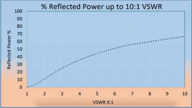
VSWR vs. % Reflected Power
In a real system, mismatched impedances cause some of the power to be reflected back toward the source (like an echo). These reflections cause constructive and destructive interference, leading to peaks and valleys in the voltage, varying with time and distance along the transmission line. VSWR quantifies these voltage variances, hence another commonly used definition for Voltage Standing Wave Ratio is that it is the ratio of the highest voltage to the lowest voltage, at any point on the transmission line.
For an ideal system, voltage does not vary. Therefore, its VSWR is 1.0 (or more usually expressed as a ratio of 1:1). When reflections occur, voltages vary and VSWR is higher, for example 1.2 (or 1.2: 1). Increased VSWR correlates with reduced transmission line (and therefore overall transmitter) efficiency.
The efficiency of transmission lines increases by:
1. Increasing voltage and power factor
2. Increasing voltage and decreasing power factor
3. Decreasing voltage and power factor
4. Decreasing voltage and increasing power factor
There are four quantities that describe the effectiveness of transferring power from a line to a load or antenna: the VSWR, the reflection coefficient, the mismatch loss, and the return loss.
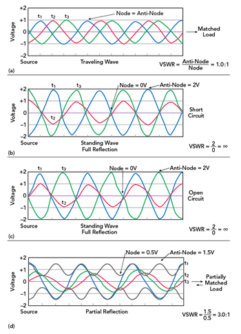
For now, to obtain a feeling for their meaning, we show them graphically on the next figure. Three conditions:
● The lines connected to a matched load;
● The lines connected to a short monopole antenna that is not matched (antenna input impedance is 20 – j80 ohms, compared to the transmission line impedance of 50 ohms);
● The line is open at the end where the antenna should have been connected.
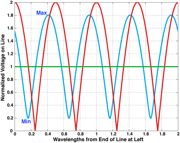
Green Curve - Standing wave on 50-ohm line with matched 50-ohm load at end
With its parameters and numericial value as follows:
| Parameters |
Numerical Value |
|
Load Impedance |
50 ohms |
|
Reflection Coefficient |
0 |
|
VSWR |
1 |
|
Mismatch Loss |
0 dB |
|
Return Loss |
– ∞ dB |
|
Notice: [This is perfect; no standing wave; all power goes into antenna/load] |
|
Blue Curve - Standing wave on 50-ohm line into short monopole antenna
With its parameters and numericial value as follows:
| Parameters |
Numerical Value |
|
Load Impedance |
20 – j80 ohms |
| Reflection Coefficient |
0.3805 – j0.7080 |
|
Absolute Value of Reflection Coefficient |
0.8038 |
|
VSWR |
9.2 |
|
Mismatch Loss |
- 4.5 dB |
|
Return Loss |
-1.9 dB |
|
Notice: [This is not too good; power into load or antenna is down –4.5 dB from that available traveling down line] |
|
Red Curve - Standing wave on line with open circuit at left end (antenna terminals)
With its parameters and numericial value as follows:
| Parameters |
Numerical Value |
|
Load Impedance |
∞ |
|
Reflection Coefficient |
1 |
|
VSWR |
∞ |
|
Mismatch Loss |
- 0 dB |
|
Return Loss |
0 dB |
|
Notice: [This is very bad: no power transferred past end of line] |
|
▲BACK▲
3. Important parameter indicators of SWR
1) Trasmission Lines and SWR
Any conductor carrying an AC current can be treated as a transmission line, such as those overhead giants distributing AC utility power across the landscape. Incorporating all the different forms of transmission lines would fall considerably outside the scope of this article, so we’ll limit the discussion to frequencies from about 1 MHz to 1 GHz, and to two common types of line: coaxial (or “coax”) and parallel-conductor (a.k.a., open-wire, window line, ladder line, or twin-lead as we’ll call it) as shown in Figure 1.
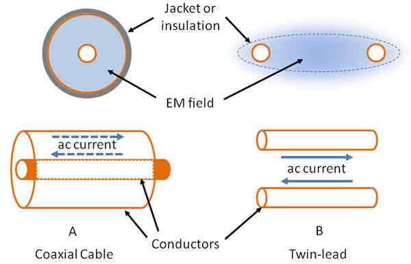
Explanatinon: Coaxial cable (A) consists of a solid or stranded center conductor surrounded by an insulating plastic or air dielectric and a tubular shield that is either solid or woven wire braid. A plastic jacket surrounds the shield to protect the conductors. Twin-lead (B) consists of a pair of parallel solid or stranded wires. The wires are held in place by either molded plastic (window line, twin-lead) or by ceramic or plastic insulators (ladder line).
Current flows along the surface of the conductors (see the sidebar on “Skin Effect”) in opposite directions. Surprisingly, the RF energy flowing along the line doesn’t really flow in the conductors where the current is. It travels as an electromagnetic (EM) wave in the space between and around the conductors.
Figure 1 indicates where the field is located in both coax and twin-lead. For coax, the field is completely contained within the dielectric between the center conductor and shield. For twin-lead, though, the field is strongest around and between the conductors but without a surrounding shield, some of the field extends into the space around the line.
This is why coax is so popular — it doesn’t allow the signals inside to interact with signals and conductors outside the line. Twin-lead, on the other hand, has to be kept well away (a few line widths is sufficient) from other feed lines and any kind of metal surface. Why use twin-lead? It generally has lower losses than coax, so is a better choice when signal loss is an important consideration.
Transmission Line Tutorial for the Beginners (Source: AT&T)
|
What is Skin Effect? |
|
Above about 1 kHz, AC currents flow in an increasingly thin layer along the surface of conductors. This is the skin effect. It occurs because eddy currents inside the conductor create magnetic fields that push current to the outer surface of the conductor. At 1 MHz in copper, most current is restricted to the conductor’s outer 0.1 mm, and by 1 GHz, current is squeezed into a layer just a few µm thick. |
2) Reflection and Transmission Coefficients
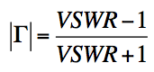
Reflection coefficient is the fraction of an incident signal reflected back from a mismatch. The reflection coefficient is expressed as either ρ or Γ, but these symbols may also be used to represent VSWR. It is directly related to the VSWR by
| Γ | = (VSWR - 1)/(VSWR + 1) (A)
Figure.That is the fraction of a signal reflected back by the load impedance, and is sometimes expressed as a percentage.
For a perfect match, no signal is reflected by the load (i.e., it is totally absorbed), so the reflection coefficient is zero.
For an open or short circuit, the entire signal is reflected back, so the reflection coefficient in both cases is 1. Note that this discussion deals only with the magnitude of the reflection coefficient.
Γ has an associated phase angle as well, which distinguishes between a short circuit and an open circuit, as well as all states in between.
For example, reflection from an open circuit results in a 0 degree phase angle between the incident and reflected wave, which means that the reflected signal adds in phase with the incoming signal at the open circuit location; i.e. the amplitude of the standing wave is double that of the incoming wave.
In contrast, a short circuit results in a 180 degree phase angle between the incident and reflected signal, which means that the reflected signal is opposite in phase to the incoming signal, so their amplitudes subtract, resulting in zero. This can be seen in Figures 1a and b.
Where the reflection coefficient is the fraction of an incident signal reflected back from an impedance mismatch in a circuit or transmission line, the transmission coefficient is the fraction of the incident signal that appears at the output.
It is a function of the signal that is reflected as well as internal circuit interactions. It has a corresponding amplitude and phase, as well.
3) What is Return Loss and Insertion Loss?
Return loss is the ratio of the power level of the reflected signal to the power level of the input signal expressed in decibels (dB), i.e.,
RL (dB) = 10 log10 Pi/Pr (B)
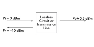
Figure 2. Return loss and insertion loss in a lossless circuit or transmission line.
In Figure 2, a 0-dBm signal, Pi, is applied to the transmission line. The power reflected, Pr, is shown as −10 dBm and the return loss is 10 dB. The higher the value, the better the match, that is, for a perfect match, the return loss, ideally, is ∞, but a return loss of 35 to 45 dB, is usually considered a good match. Similarly, for an open circuit or a short circuit, the incident power is reflected back. The return loss for these cases is 0 dB.
Insertion loss is the ratio of the power level of the transmitted signal to the power level of the input signal expressed in decibels (dB), i.e.,
IL (dB) = 10 log10 Pi/Pt (C)
Pi = Pt + Pr ; Pt/Pi + Pr/Pi = 1
Referring to Figure 2, Pr of -10 dBm means that 10 percent of the incident power is reflected. If the circuit or transmission line is lossless, 90 percent of the incident power is transmitted. The insertion loss is therefore approximately 0.5 dB, resulting in a transmitted power of -0.5 dBm. If there were internal losses, the insertion loss would be greater.
4) What is S-parameters?
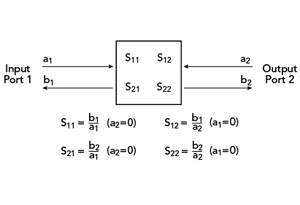 Figure. S-parameter representation of a two port microwave circuit.
Using S-parameters, a circuit’s RF performance can be completely characterized without the need to know its internal composition. For these purposes, the circuit is commonly referred to as a “black box.” Internal components can be active (i.e., amplifiers) or passive. The only stipulations are that the S-parameters are determined for all frequencies and conditions (e.g., temperature, amplifier bias) of interest and that the circuit be linear (i.e, its output is directly proportional to its input). Figure 3 is a representation of a simple microwave circuit with one input and one output (called ports). Each port has an incident signal (a) and a reflected signal (b). By knowing the S-parameters (i.e., S11, S21, S12, S22) of this circuit, one can determine its effect on any system in which it is installed.
S-parameters are determined by measurement under controlled conditions. Using a special piece of test equipment called a network analyzer, a signal (a1) is input into Port 1 with Port 2 terminated in a system with a controlled impedance (typically 50 ohms). The analyzer simultaneously measures and records a1, b1 and b2 (a2 = 0). The process is then reversed, i.e. with a signal (a2) input to Port 2, the analyzer measures a2, b2 and b1 (a1 = 0). In its simplest form, the network analyzer measures only the amplitudes of these signals. This is called a scalar network analyzer and is sufficient for determining quantities such as VSWR, RL and IL. For complete circuit characterization, however, phase is needed as well and requires the use of a vector network analyzer. The S-parameters are determined by the following relationships:
S11 = b1/a1 ; S21 = b2/a1 ; S22 = b2/a2 ; S12 = b1/a2 (D)
S11 and S22 are the circuit’s input and output port reflection coefficients, respectively; while S21 and S12 are the circuit’s forward and reverse transmission coefficients. RL is related to the reflection coefficients by the relationships
RLPort 1 (dB) = -20 log10 | S11| and RLPort 2 (dB) = -20 log10 | S22| (E)
IL is related to the circuits transmission coefficients by the relationships
ILfrom Port 1 to Port 2 (dB) = -20 log10 | S21| and ILfrom Port 2 to Port 1 (dB) = -20 log10 | S12| (F)
This representation can be extended to microwave circuits with an arbitrary number of ports. The number of S-parameters goes up by the square of the number of ports, so the mathematics becomes more involved, but is manageable using matrix algebra.
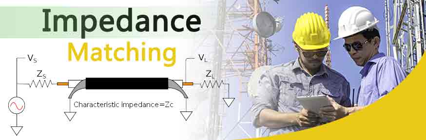
5) What is Impedance-Matching?
Impedance is opposition encountered by electrical energy as it moves away from its source.
Synchronizing load and source impedance will cancel out the effect leading to maximum power transfer.
This is known as the maximum power transfer theorem: Maximum power transfer theorem is critical in radiofrequency transmission assemblies, and in particular, in the set up of RF antennas.
Impedance matching is critical to the efficient functioning of RF setups where you want to move voltage and power optimally. In RF design, the matching of source and load impedances will maximize the transmission of RF power. Antennas will receive maximum or optimal power transfer where their impedance is matched to the output impedance of the transmission source.
50Ohm impedance is the standard for designing most RF systems and components. Coaxial cable which underpins the connectivity in a range of RF applications has a typical impedance of 50 Ohms. RF research undertaken in the 1920s found that optimal impedance for the transfer of RF signals would be between 30 and 60Ohms depending on voltage and power transfer. Having relatively standardized impedance allows matching between cabling and components such as WiFi or Bluetooth antennas, PCBs and attenuators. A number of key antenna types have an impedance of 50 Ohms including ZigBee GSM GPS and LoRa
Reflection Coefficient - Source: Wikipedia
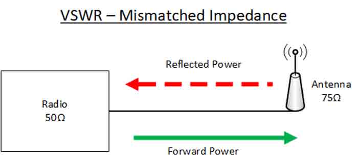
A mismatch in impedance leads to voltage and current reflections, and in RF setups this means that signal power will be reflected back to its source, the proportion being according to the degree of mismatch. This can be characterized using Voltage Standing Wave Ratio (V.S.W.R.) which is a measure of the efficiency of transfer of RF power from its source into a load, such as an antenna.
Mismatching between source and load impedances, for example a 75Ohm antenna and 50 Ohm coax cabling, can be overcome using a range of impedance matching devices such as resistors in series, transformers, surface mounted impedance matching pads or antenna tuners.
In electronics, impedance matching involves creating or altering a circuit or electronic application or component set up so that the impedance of the electrical load matches the impedance of the power or driving source. The circuit is engineered or geared so that the impedances appear the same.
When looking at systems that include transmission lines it is necessary to understand that sources, transmission lines / feeders and loads all have a characteristic impedance. 50Ω is a very common standard for RF applications although other impedances may occasionally be seen in some systems.
In order to obtain the maximum power transfer from the source to the transmission line, or the transmission line to the load, be it a resistor, an input to another system, or an antenna, the impedance levels must match.
In other words for a 50Ω system the source or signal generator must have a source impedance of 50Ω, the transmission line must be 50Ω and so must the load.
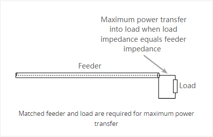
Issues arise when power is transferred into the transmission line or feeder and it travels towards the load. If there is a mismatch, i.e. the load impedance does not match that of the transmission line, then it is not possible for all the power to be transferred.
As power cannot disappear, the power that is not transferred into the load has to go somewhere and there it travels back along the transmission line back towards the source.
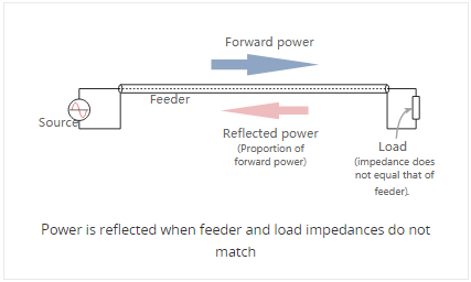
When this happens the voltages and currents of the forward and reflected waves in the feeder add or subtract at different points along the feeder according to the phases. In this way standing waves are set up.
The way in which the effect occurs can be demonstrated with a length of rope. If one end is left free and the other is moved up an down the wave motion can be seen to move down along the rope. However if one end is fixed a standing wave motion is set up, and points of minimum and maximum vibration can be seen.
When the load resistance is lower than the feeder impedance voltage and current magnitudes are set up. Here the total current at the load point is higher than that of the perfectly matched line, whereas the voltage is less.
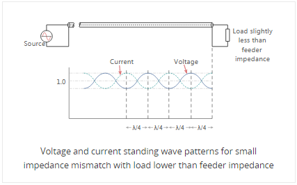
The values of current and voltage along the feeder vary along the feeder. For small values of reflected power the waveform is almost sinusoidal, but for larger values it becomes more like a full wave rectified sine wave. This waveform consists of voltage and current from the forward power plus voltage and current from the reflected power.
At a distance a quarter of a wavelength from the load the combined voltages reach a maximum value whilst the current is at a minimum. At a distance half a wavelength from the load the voltage and current are the same as at the load.
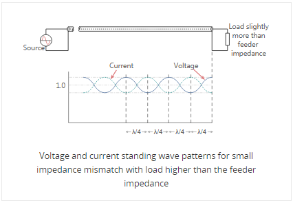
A similar situation occurs when the load resistance is greater than the feeder impedance however this time the total voltage at the load is higher than the value of the perfectly matched line. The voltage reaches a minimum at a distance a quarter of a wavelength from the load and the current is at a maximum. However at a distance of a half wavelength from the load the voltage and current are the same as at the load.
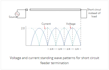
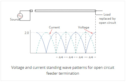
Then when there is an open circuit placed at the end of the line, the standing wave pattern for the feeder is similar to that of the short circuit, but with the voltage and current patterns reversed.
▲BACK▲
6) What is Reflected Energy?
When a transmitted wave hits a boundary such as the one between the lossless transmission line and load (See Figure 1. below), some energy will be transmitted to the load and some will be reflected. The reflection coefficient relates the incoming and reflected waves as:
Γ = V-/V+ (Eq. 1)
Where V- is the reflected wave and V+ is the incoming wave. VSWR is related to the magnitude of the voltage reflection coefficient (Γ) by:
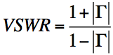
VSWR = (1 + |Γ|)/(1 – |Γ|) (Eq. 2)
VSWR can be measured directly with an SWR meter. An RF test instrument such as a vector network analyzer (VNA) can be used to measure the reflection coefficients of the input port (S11) and the output port (S22). S11 and S22 are equivalent to Γ at the input and output port, respectively. The VNAs with math modes can also directly calculate and display the resulting VSWR value.
The return loss at the input and output ports can be calculated from the reflection coefficient, S11 or S22, as follows:
RLOUT = 20log10|S22| dB (Eq. 4)
The reflection coefficient is calculated from the characteristic impedance of the transmission line and the load impedance as follows:
Γ = (ZL - ZO)/(ZL + ZO) (Eq. 5)
Where ZL is the load impedance and ZO is the characteristic impedance of the transmission line (Figure 1).
VSWR can also be expressed in terms of ZL and ZO. Substituting Equation 5 into Equation 2, we obtain:
VSWR = [1 + |(ZL - ZO)/(ZL + ZO)|]/[1 - |(ZL - ZO)/(ZL + ZO)|] = (ZL + ZO + |ZL - ZO|)/(ZL + ZO - |ZL - ZO|)
For ZL > ZO, |ZL - ZO| = ZL - ZO
Therefore:
VSWR = (ZL + ZO + ZL - ZO)/(ZL + ZO - ZL + ZO) = ZL/ZO. (Eq. 6)
For ZL < ZO, |ZL - ZO| = ZO - ZL
Therefore:
VSWR = (ZL + ZO + ZO - ZL)/(ZL + ZO - ZO + ZL) = ZO/ZL. (Eq. 7)
We noted above that VSWR is a specification given in ratio form relative to 1, as an example 1.5:1. There are two special cases of VSWR, ∞:1 and 1:1. A ratio of infinity to one occurs when the load is an open circuit. A ratio of 1:1 occurs when the load is perfectly matched to the transmission-line characteristic impedance.
VSWR is defined from the standing wave that arises on the transmission line itself by:
VSWR = |VMAX|/|VMIN| (Eq. 8)
Where VMAX is the maximum amplitude and VMIN is the minimum amplitude of the standing wave. With two super-imposed waves, the maximum occurs with constructive interference between the incoming and reflected waves. Thus:
VMAX = V+ + V- (Eq. 9)
for maximum constructive interference. The minimum amplitude occurs with deconstructive interference, or:
VMIN = V+ - V- (Eq. 10)
Substituting Equations 9 and 10 into Equation 8 yields
VSWR = |VMAX|/|VMIN| = (V+ + V-)/(V+ - V-) (Eq. 11)
Substitute Equation 1 into Equation 11, we obtain:
VSWR = V+(1 + |Γ|)/(V+(1 - |Γ|) = (1 + |Γ|)/(1 – |Γ|) (Eq. 12)
Equation 12 is Equation 2 stated at the beginning of this article.
▲BACK▲
4. VSWR Calculator: How to Calculate VSWR?
Impedance mismatches result in standing waves along the transmission line, and SWR is defined as the ratio of the partial standing wave's amplitude at an antinode (maximum) to the amplitude at a node (minimum) along the line.
The resulting ratio is normally expressed as a ratio, e.g. 2:1, 5:1, etc. A perfect match is 1:1 and a complete mismatch, i.e. a short or open circuit is ∞:1.
In practice there is a loss on any feeder or transmission line. To measure the VSWR, forward and reverse power is detected at that point on the system and this is converted to a figure for VSWR.
In this way, the VSWR is measured at a particular point and the voltage maxima and minima do not need to be determined along the length of the line.
The voltage component of a standing wave in a uniform transmission line consists of the forward wave (with amplitude Vf) superimposed on the reflected wave (with amplitude Vr). Reflections occur as a result of discontinuities, such as an imperfection in an otherwise uniform transmission line, or when a transmission line is terminated with other than its characteristic impedance.
If you are interested in determining the performance of antennas, the VSWR should always be measured at the antenna terminals themselves rather than at the output of the transmitter. Because of ohmic losses in the transmit cabling, an illusion will be created of having a better antenna VSWR, but that is only because these losses damp the impact of an abrupt reflection at the antenna terminals.
Since the antenna is usually located some distance from the transmitter, it requires a feed line to transfer power between the two. If the feed line has no loss and matches both the transmitter output impedance and the antenna input impedance, then the maximum power will be delivered to the antenna. In this case, the VSWR will be 1:1 and the voltage and the current will be constant over the whole length of the feed line.
Return loss is a measure in dB of the ratio of power in the incident wave to that in the reflected wave, and we define it to have a negative value.
Return loss = 10 log(Pr / Pi) = 20 log (Er / Ei)
For example, if a load has a return loss of -10 dB, then 1/10 of the incident power is reflected. The higher the return loss, the less power is actually lost.
Also of considerable interest is the mismatch loss. This is a measure of how much the transmitted power is attenuated due to reflection. It is given by the following relation:
Mismatch Loss = 10 log ( 1 -p2)
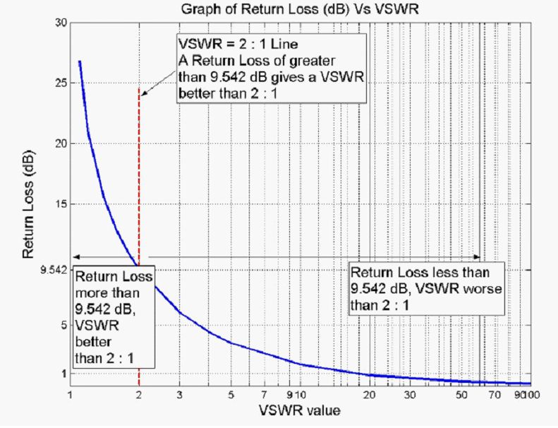
For example, from Table #1 an antenna with a VSWR of 2:1 would have a reflection coefficient of 0.333, a mismatch loss of -0.51 dB, and a return loss of -9.54 dB (11% of your transmitter power is reflected back)
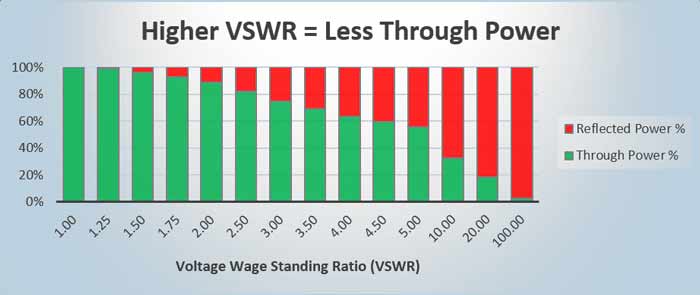
2) Free VSWR Caculation Chart
Here's a simple VSWR calculation chart.
|
Always remeber that VSWR should be a number larger than 1.0
|
||||||
| VSWR | Reflection Coefficient (Γ) | Reflected Power (%) |
Voltage Loss |
Reflected Power (dB) |
Return Loss |
Mismatch Loss (dB) |
|
1 |
0.00 | 0.00 | 0 | -Infinity | Infinity |
0.00 |
|
1.15 |
0.070 | 0.5 | 7.0 | -23.13 | 23.13 | 0.021 |
| 1.25 | 0.111 | 1.2 | 11.1 | -19.08 | 19.08 |
0.054 |
|
1.5 |
0.200 | 4.0 | 20.0 | -13.98 | 13.98 | 0.177 |
| 1.75 | 0.273 | 7.4 |
273. |
-11.73 | 11.29 | 0.336 |
| 1.9 |
0.310 |
9.6 | 31.6 | -10.16 | 10.16 | 0.440 |
| 2.0 | 0.333 |
11.1 |
33.3 | -9.54 | 9.540 | 0.512 |
| 2.5 | 0.429 | 18.4 | 42.9 | -7.36 | 7.360 | 0.881 |
| 3.0 | 0.500 | 25.0 | 50.0 | -6.02 | 6.021 | 1.249 |
|
3.5 |
0.555 | 30.9 | 55.5 | -5.11 | 5.105 | 1.603 |
|
4.0 |
0.600 | 36.0 | 60.0 |
-4.44 |
4.437 | 1.938 |
|
4.5 |
0.636 | 40.5 | 63.6 | -3.93 |
3.926 |
2.255 |
| 5.0 | 0.666 | 44.4 | 66.6 | -3.52 | 3.522 | 2.553 |
| 10 | 0.818 | 66.9 | 81.8 | -1.74 | 1.743 | 4.807 |
| 20 | 0.905 | 81.9 | 90.5 | -0.87 | 0.8693 | 7.413 |
| 100 | 0.980 | 96.1 | 98.0 | -0.17 | 0.1737 | 14.066 |
| ... | ... | ... | ... | ... |
... |
... |
|
∞ |
∞ |
100 |
100 |
∞ |
∞ |
∞ |
|
Extra Reading: VSWR in antenna
The Voltage Standing Wave Ratio (VSWR) is an indication of the amount of mismatch between an antenna and the feed line connecting to it. This is also known as the Standing Wave Ratio (SWR). The range of values for VSWR is from 1 to ∞ .
A VSWR value under 2 is considered suitable for most antenna applications. The antenna can be described as having a “Good Match”. So when someone says that the antenna is poorly matched, very often it means that the VSWR value exceeds 2 for a frequency of interest.
Return loss is another specification of interest and is covered in more detail in the Antenna Theory section. A commonly required conversion is between return loss and VSWR, and some values are tabulated in chart, along with a graph of these values for quick reference. |
||||||
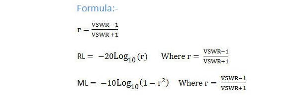
Where do these calculations come from? Well, start with the formula for VSWR:
If we invert this formula, we can calculate the reflection coefficient (, or the return loss, s11) from the VSWR:
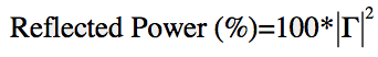
Now, this reflection coefficient is actually defined in terms of voltage. We really want to know how much power is being reflected. This will be proportional to the square of the voltage (V^2). Hence, the reflected power in percent will be:
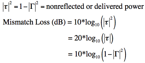
We can convert reflected power to decibels simply:

Finally, the power is either reflected or delivered to the antenna. The amount delivered to the antenna is written as (), and is simply (1-^2). This is known as mismatch loss. This is the amount of power that is lost due to impedance mismatch, and we can calculate that fairly easily:
And that's all we need to know to go back and forth between VSWR, s11/return loss, and mismatch loss. I hope you've had as great of a time as I've had.
Conversion table – dBm to dBW and W (watt)
In this table we present how the value of power in dBm, dBW and Watt (W) corresponding to each other.
|
Power (dBm) |
Power (dBW) |
Power ((W)watt) |
|
100 |
70 |
10 MW |
|
90 |
60 |
1 MW |
|
80 |
50 |
100 KW |
|
70 |
40 |
10 KW |
|
60 |
30 |
1 KW |
|
50 |
20 |
100 W |
|
40 |
10 |
10 W |
|
30 |
0 |
1 W |
|
20 |
-10 |
100 mW |
|
10 |
-20 |
10 mW |
|
0 |
-30 |
1 mW |
|
-10 |
-40 |
100 μW |
|
-20 |
-50 |
10 μW |
|
-30 |
-60 |
1 μW |
|
-40 |
-70 |
100 nW |
|
-50 |
-80 |
10 nW |
|
-60 |
-90 |
1 nW |
|
-70 |
-100 |
100 pW |
|
-80 |
-110 |
10 pW |
|
-90 |
-120 |
1 pW |
|
-100 |
-130 |
0.1 pW |
|
-∞ |
-∞ |
0 W |
|
where: dBm = decibel-milliwatt dBW = decibel-watt MW = megawatt KW = kilowatt W = watt mW = milliwatt μW = microwatt nW = nanowatt pW = picowatt |
||
▲BACK▲
3) VSWR Formula
This program is an applet for calculating the Voltage Standing Wave Ratio (VSWR).
When setting up an antenna and transmitter system, it is important to avoid impedance mismatching anywhere in the system. Any mismatch means some proportion of the output wave is reflected back toward the transmitter and the system becomes inefficient. Mismatches can occur at interfaces between various equipment e.g. transmitter, cable and antenna. Antennas have impedance, which is typically 50 ohms (when antenna is of the correct dimensions). When reflection occurs, standing waves are produced in the cable.
VSWR formula and reflection coefficient:
|
Eq.1 |
Reflection coefficient Γ is defined as |
Eq.2 |
The VSWR or voltage standing wave ratio |
| Formula |
 |
Formula |
 |
|
Gamma |
ZL = The value in ohms of the load (typically an antenna) Zo = The Characteristic impedance of the transmission line in ohms |
Sigma |
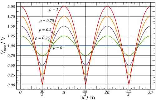
Given that ρ will vary from 0 to 1, the calculated values for VSWR will be from 1 through to infinity. |
|
Calculated values |
between -1 ≦ Γ ≦ 1. |
Calculated values |
1 or a 1:1 ratio. |
|
When value is “-1”. |
Means 100% reflection occurs and no power is transferred to the load. The reflected wave is 180 degrees out of phase (inverted) with the incident wave. |
With open circuit |
This is an open circuit condition with no antenna connected. It means that ZL is infinite and the terms Zo will disappear in Eq.1, leaving Γ=1 (100% reflection) and ρ=1.
|
|
When value is “1”. |
Means 100% reflection occurs and no power is transferred to the load. The reflected wave is in phase with the incident wave. |
With short circuit |
Imagine the end of the cable has a short circuit. It means ZL is 0 and the Eq.1 will calculate Γ=-1 and ρ=1.
|
|
When value is “0”. |
Means no reflection occurs and all power is transferred to the load. (IDEAL) |
With correctly matched antenna. |
When a correctly matched antenna is connected, then all energy is transferred to the antenna and is converted to radiation. ZL is 50 ohms and Eq.1 will calculate Γ to be zero. Thus VSWR will be exactly 1. |
| N/A | N/A |
With incorrectly matched antenna. |
When an incorrectly matched antenna is connected, the impedance will no longer be 50 ohms and an impedance mismatch occurs and part of the energy is reflected back. The amount of energy reflected depends on the level of the mismatch and so VSWR will be a value above 1. |
When using cable of incorrect characteristic impedance
The cable / transmission line used to connect the antenna to the transmitter will need to be the correct characteristic impedance Zo.
Typically, coaxial cables are 50ohms (75ohms for televisions and satellite) and their values will be printed on the cables themselves.
The amount of energy reflected depends on the level of the mismatch and so VSWR will be a value above 1. |
|||

Review:
What are standing waves? A load is connected to the end of the transmission line and the signal flows along it and enters the load. If the load impedance does not match with the transmission line impedance, then part of the travelling wave is reflected back towards the source.
When reflection occurs, these travel back down the transmission line and combine with the incident waves to produce standing waves. It is important to note that the resultant wave appears stationary like and does not propagate like a normal wave and does not transfer energy toward the load. The wave has areas of maximum and minimum amplitude called anti-nodes and nodes respectively.
When connecting the antenna, if a VSWR of 1.5 is produced, then power efficiency is 96%. When a VSWR of 3.0 is produced, then the power efficiency is 75%. In actual use, it is not recommended to exceed a VSWR of 3.
▲BACK▲
5. How to Measure Standing Wave Ratio - Wikipedia Explanation
Many different methods can be used to measure standing wave ratio. The most intuitive method uses a slotted line which is a section of transmission line with an open slot which allows a probe to detect the actual voltage at various points along the line.
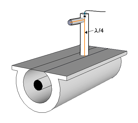
Thus the maximum and minimum values can be compared directly. This method is used at VHF and higher frequencies. At lower frequencies, such lines are impractically long. Directional couplers can be used at HF through microwave frequencies.
Some are a quarter wave or more long, which restricts their use to the higher frequencies. Other types of directional couplers sample the current and voltage at a single point in the transmission path and mathematically combine them in such a way as to represent the power flowing in one direction.
The common type of SWR/power meter used in amateur operation may contain a dual directional coupler. Other types use a single coupler which can be rotated 180 degrees to sample power flowing in either direction. Unidirectional couplers of this type are available for many frequency ranges and power levels and with appropriate coupling values for the analog meter used.
A directional wattmeter using a rotatable directional coupler element
The forward and reflected power measured by directional couplers can be used to calculate SWR. The computations can be done mathematically in analog or digital form or by using graphical methods built into the meter as an additional scale or by reading from the crossing point between two needles on the same meter.
The above measuring instruments can be used "in line" that is, the full power of the transmitter can pass through the measuring device so as to allow continuous monitoring of SWR. Other instruments, such as network analyzers, low power directional couplers and antenna bridges use low power for the measurement and must be connected in place of the transmitter. Bridge circuits can be used to directly measure the real and imaginary parts of a load impedance and to use those values to derive SWR. These methods can provide more information than just SWR or forward and reflected power.[11] Stand alone antenna analyzers use various measuring methods and can display SWR and other parameters plotted against frequency. By using directional couplers and a bridge in combination, it is possible to make an in line instrument that reads directly in complex impedance or in SWR.[12] Stand alone antenna analyzers also are available that measure multiple parameters.
▲BACK▲
1) What Causes High VSWR?
If the VSWR is too high, there could potentially be too much energy reflected back into a power amplifier, causing damage to the internal circuitry. In an ideal system, there would be a VSWR of 1:1. Causes of a high VSWR rating could be use of an improper load or something unknown such as a damaged transmission line.
2) How do You Reduce VSWR?
One technique to reduce the reflected signal from the input or output of any device is to place an attenuator before or after the device. The attenuator reduces the reflected signal two times the value of the attenuation, while the transmitted signal receives the nominal attenuation value. (Tips: To stress how important VSWR and RL are to your network, consider a reduction in performance from VSWR of 1.3:1 to 1.5:1 - this is a change in Return Loss of 16 dB to 13 dB).
3) Is S11 Return Loss?
In practice, the most commonly quoted parameter in regards to antennas is S11. S11 represents how much power is reflected from the antenna, and hence is known as the reflection coefficient (sometimes written as gamma: or return loss. ... This accepted power is either radiated or absorbed as losses within the antenna.
4) Why VSWR is Measured?
VSWR (Voltage Standing Wave Ratio), is a measure of how efficiently radio-frequency power is transmitted from a power source, through a transmission line, into a load (for example, from a power amplifier through a transmission line, to an antenna). In an ideal system, 100% of the energy is transmitted.
5) How do I Fix High VSWR?
If your antenna is mounted down low on the vehicle, like on the bumper or behind a pickup truck's cab, the signal can bounce back to the antenna, causing a high SWR. To alleviate this, keep at least the top 12 inches of the antenna above the roof line, and position the antenna as high as possible on the vehicle.
The best reading possible is 1.01:1 (46dB return loss), but usually a reading below 1.5:1 is acceptable. Outside the perfect world a 1.2:1 (20.8dB return loss) is spot on in most cases. To ensure an accurate reading, it is best to connect the meter at the base of the antenna.
7) Is 1.5 SWR Good?
Yes, it is! The ideal range is SWR 1.0-1.5. There's room for improvement when the range is SWR 1.5 - 1.9, but SWR in this range should still provide adequate performance. Occasionally, due to installations or vehicle variables, it's impossible to get SWR lower than than this.
8) How do I Check My SWR Without a Meter?
Here are the steps To tune a CB radio without an SWR meter:
1) Find an area with limited interference.
2) Make sure you have an additional radio.
3) Tune both radios to the same channel.
4) Speak into one radio and listen through the other.
5) Move one radio away and note when the sound is clear.
6) Adjust your antenna as needed.
9) Do all CB Antennas Need to be Tuned?
While antenna tuning isn't required to operate your CB system, there are a number of important reasons you should always tune an antenna: Improved Performance - A properly tuned antenna will ALWAYS work more efficiently than an untuned antenna.
10) Why does My SWR Go up When I talk?
One of the most common causes of high SWR readings is incorrectly connecting your SWR meter to your radio and antenna. When attached incorrectly, readings will be reported as being extremely high even if everything is installed perfectly. Please see this article on ensuring your SWR meter is properly installed.
7. Best Free Online VSWR Calculator in 2021
https://www.microwaves101.com/calculators/872-vswr-calculator
http://rfcalculator.mobi/vswr-forward-reverse-power.html
https://www.everythingrf.com/rf-calculators/vswr-calculator
https://www.pasternack.com/t-calculator-vswr.aspx
https://www.antenna-theory.com/definitions/vswr-calculator.php
http://www.flexautomotive.net/flexcalc/VSWR2/VSWR.aspx
https://www.allaboutcircuits.com/tools/vswr-return-loss-calculator/
http://www.csgnetwork.com/vswrlosscalc.html
https://www.ahsystems.com/EMC-formulas-equations/VSWR.php
http://cgi.www.telestrian.co.uk/cgi-bin/www.telestrian.co.uk/vswr.pl
https://www.changpuak.ch/electronics/calc_14.php
https://chemandy.com/calculators/return-loss-and-mismatch-calculator.htm
https://www.atmmicrowave.com/calculator/vswr-calculator/
http://www.emtalk.com/vswr.php
▲BACK▲
Sharing is caring!
