
Products Category
- FM Transmitter
- 0-50w 50w-1000w 2kw-10kw 10kw+
- TV Transmitter
- 0-50w 50-1kw 2kw-10kw
- FM Antenna
- TV Antenna
- Antenna Accessory
- Cable Connector Power Splitter Dummy Load
- RF Transistor
- Power Supply
- Audio Equipments
- DTV Front End Equipment
- Link System
- STL system Microwave Link system
- FM Radio
- Power Meter
- Other Products
- Special for Coronavirus
Products Tags
Fmuser Sites
- es.fmuser.net
- it.fmuser.net
- fr.fmuser.net
- de.fmuser.net
- af.fmuser.net ->Afrikaans
- sq.fmuser.net ->Albanian
- ar.fmuser.net ->Arabic
- hy.fmuser.net ->Armenian
- az.fmuser.net ->Azerbaijani
- eu.fmuser.net ->Basque
- be.fmuser.net ->Belarusian
- bg.fmuser.net ->Bulgarian
- ca.fmuser.net ->Catalan
- zh-CN.fmuser.net ->Chinese (Simplified)
- zh-TW.fmuser.net ->Chinese (Traditional)
- hr.fmuser.net ->Croatian
- cs.fmuser.net ->Czech
- da.fmuser.net ->Danish
- nl.fmuser.net ->Dutch
- et.fmuser.net ->Estonian
- tl.fmuser.net ->Filipino
- fi.fmuser.net ->Finnish
- fr.fmuser.net ->French
- gl.fmuser.net ->Galician
- ka.fmuser.net ->Georgian
- de.fmuser.net ->German
- el.fmuser.net ->Greek
- ht.fmuser.net ->Haitian Creole
- iw.fmuser.net ->Hebrew
- hi.fmuser.net ->Hindi
- hu.fmuser.net ->Hungarian
- is.fmuser.net ->Icelandic
- id.fmuser.net ->Indonesian
- ga.fmuser.net ->Irish
- it.fmuser.net ->Italian
- ja.fmuser.net ->Japanese
- ko.fmuser.net ->Korean
- lv.fmuser.net ->Latvian
- lt.fmuser.net ->Lithuanian
- mk.fmuser.net ->Macedonian
- ms.fmuser.net ->Malay
- mt.fmuser.net ->Maltese
- no.fmuser.net ->Norwegian
- fa.fmuser.net ->Persian
- pl.fmuser.net ->Polish
- pt.fmuser.net ->Portuguese
- ro.fmuser.net ->Romanian
- ru.fmuser.net ->Russian
- sr.fmuser.net ->Serbian
- sk.fmuser.net ->Slovak
- sl.fmuser.net ->Slovenian
- es.fmuser.net ->Spanish
- sw.fmuser.net ->Swahili
- sv.fmuser.net ->Swedish
- th.fmuser.net ->Thai
- tr.fmuser.net ->Turkish
- uk.fmuser.net ->Ukrainian
- ur.fmuser.net ->Urdu
- vi.fmuser.net ->Vietnamese
- cy.fmuser.net ->Welsh
- yi.fmuser.net ->Yiddish
Basic Theory on FM
Common Applications
Frequency modulation (FM) is most commonly used for radio and television broadcast. The FM band is divided between a variety of purposes. Analog television channels 0 through 72 utilize bandwidths between 54 MHz and 825 MHz. In addition, the FM band also includes FM radio, which operates from 88 MHz to 108 MHz. Each radio station utilizes a 38 kHz frequency band to broadcast audio.
FM Theory
The basic principle behind FM is that the amplitude of an analog baseband signal can be represented by a slightly different frequency of the carrier. We represent this relationship in the graph below.
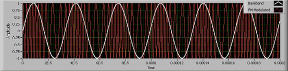
Figure 1. Frequency Modulation
First, we represent our message, or baseband, signal by the simple designation m(t). Second, we represent a sinusoidal carrier by the equation:
xc(t) = Ac cos (2πfct).
The actual mathematical process to modulate a baseband signal, m(t), onto the carrier requires a two-step process. First, the message signal must be integrated with respect to time to get an equation for phase with respect to time, θ(t). This integration enables the modulation process because phase modulation is fairly straightforward with typical I/Q modulator circuitry. A block diagram description of an FM transmitter follows.
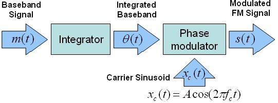
Figure 2. FM Transmitter Block Diagram
where kf is the frequency sensitivity. Again, the resulting modulation that must occur is phase modulation, which involves changing the phase of the carrier over time. This process is fairly straightforward and requires a quadrature modulator, shown below.
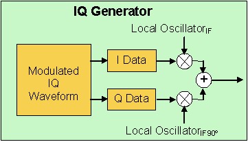
Figure 3. Quadrature Modulator
where m(τ) = M cos (2πfmτ). More simply, we can also represent this equation as:
Modulation Index
One important aspect of frequency modulation is the modulation index. We already have established that changes in amplitude of the baseband correspond to changes in carrier frequency. The factor that determines exactly how much the carrier deviates from its center frequency is known as the modulation index. Mathematically, we have already identified our integrated baseband signal as the following equation.
We can simplify this equation to the following:
In the equation above, ∆ƒ is the frequency deviation, which represents the maximum frequency difference between the instantaneous frequency and the carrier frequency. In fact, the ratio of ∆ƒ to the carrier frequency is the modulation index. This index, β, is thus defined by the equation
The integrated message signal can be represented as:
As a result, we can substitute this new representation of θ(t) into our original formula to represent the final modulated FM signal as the following equation:
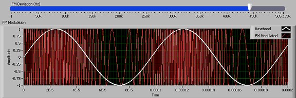
Figure 4. FM Signal with 425 kHz FM Deviation
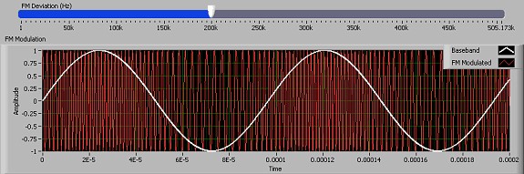
Figure 5. FM Signal with 200 kHz FM Deviation
This property can be more fully observed by selecting the FM example.
Conclusions
Frequency Modulation (FM) is an important modulation scheme both because of its widespread commercial use, and because of its simplicity. As we have seen in this document, frequency modulation can be simplified to angle modulation with a simple integrator. As a result, we can generate frequency modulated signals with the National Instruments vector signal generator, because they require nothing more than an I/Q modulator.
