
Products Category
- FM Transmitter
- 0-50w 50w-1000w 2kw-10kw 10kw+
- TV Transmitter
- 0-50w 50-1kw 2kw-10kw
- FM Antenna
- TV Antenna
- Antenna Accessory
- Cable Connector Power Splitter Dummy Load
- RF Transistor
- Power Supply
- Audio Equipments
- DTV Front End Equipment
- Link System
- STL system Microwave Link system
- FM Radio
- Power Meter
- Other Products
- Special for Coronavirus
Products Tags
Fmuser Sites
- es.fmuser.net
- it.fmuser.net
- fr.fmuser.net
- de.fmuser.net
- af.fmuser.net ->Afrikaans
- sq.fmuser.net ->Albanian
- ar.fmuser.net ->Arabic
- hy.fmuser.net ->Armenian
- az.fmuser.net ->Azerbaijani
- eu.fmuser.net ->Basque
- be.fmuser.net ->Belarusian
- bg.fmuser.net ->Bulgarian
- ca.fmuser.net ->Catalan
- zh-CN.fmuser.net ->Chinese (Simplified)
- zh-TW.fmuser.net ->Chinese (Traditional)
- hr.fmuser.net ->Croatian
- cs.fmuser.net ->Czech
- da.fmuser.net ->Danish
- nl.fmuser.net ->Dutch
- et.fmuser.net ->Estonian
- tl.fmuser.net ->Filipino
- fi.fmuser.net ->Finnish
- fr.fmuser.net ->French
- gl.fmuser.net ->Galician
- ka.fmuser.net ->Georgian
- de.fmuser.net ->German
- el.fmuser.net ->Greek
- ht.fmuser.net ->Haitian Creole
- iw.fmuser.net ->Hebrew
- hi.fmuser.net ->Hindi
- hu.fmuser.net ->Hungarian
- is.fmuser.net ->Icelandic
- id.fmuser.net ->Indonesian
- ga.fmuser.net ->Irish
- it.fmuser.net ->Italian
- ja.fmuser.net ->Japanese
- ko.fmuser.net ->Korean
- lv.fmuser.net ->Latvian
- lt.fmuser.net ->Lithuanian
- mk.fmuser.net ->Macedonian
- ms.fmuser.net ->Malay
- mt.fmuser.net ->Maltese
- no.fmuser.net ->Norwegian
- fa.fmuser.net ->Persian
- pl.fmuser.net ->Polish
- pt.fmuser.net ->Portuguese
- ro.fmuser.net ->Romanian
- ru.fmuser.net ->Russian
- sr.fmuser.net ->Serbian
- sk.fmuser.net ->Slovak
- sl.fmuser.net ->Slovenian
- es.fmuser.net ->Spanish
- sw.fmuser.net ->Swahili
- sv.fmuser.net ->Swedish
- th.fmuser.net ->Thai
- tr.fmuser.net ->Turkish
- uk.fmuser.net ->Ukrainian
- ur.fmuser.net ->Urdu
- vi.fmuser.net ->Vietnamese
- cy.fmuser.net ->Welsh
- yi.fmuser.net ->Yiddish
The 50 Ω Question: Impedance Matching in RF Design
Real-Life RF Signals
Impedance matching is a fundamental aspect of RF design and testing; the signal reflections caused by mismatched impedances can lead to serious problems.
Matching seems like a trivial exercise when you’re dealing with a theoretical circuit composed of an ideal source, a transmission line, and a load.
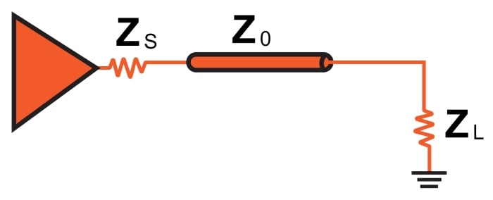
Let’s assume that the load impedance is fixed. All we need to do is include a source impedance (ZS) equal to ZL and then design the transmission line so that its characteristic impedance (Z0) is also equal to ZL.
But let’s consider for a moment the difficulty of implementing this scheme throughout a complex RF circuit consisting of numerous passive components and integrated circuits. The RF design process would be seriously unwieldy if engineers had to modify every component and specify the dimensions of every microstrip according to the one impedance chosen as the basis for all the others.
Also, this assumes that the project has already reached the PCB stage. What if we want to test and characterize a system using discrete modules, with off-the-shelf cables as interconnects? Compensating for mismatched impedances is even more impractical under these circumstances.
The solution is simple: choose a standardized impedance that can be used in numerous RF systems, and ensure that components and cables are designed accordingly. This impedance has been chosen; the unit is ohms, and the number is 50.
Fifty Ohms
The first thing to understand is that there is nothing intrinsically special about a 50 Ω impedance. This is not a fundamental constant of the universe, though you might get the impression that it is if you spend enough time around RF engineers. It is not even a fundamental constant of electrical engineering—remember, for example, that simply changing the physical dimensions of a coaxial cable will alter the characteristic impedance.
Nevertheless, 50 Ω impedance is very important, because it is the impedance around which most RF systems are designed. It is difficult to determine exactly why 50 Ω became the standardized RF impedance, but it’s reasonable to assume that 50 Ω was found to be a good compromise in the context of early coaxial cables.
The important issue, of course, is not the origin of the specific value but rather the benefits of having this standardized impedance. Achieving a well-matched design is vastly simpler because manufacturers of ICs, fixed attenuators, antennas, and so forth can build their parts with this impedance in mind. Also, PCB layout becomes more straightforward because so many engineers have the same goal, namely, to design microstrips and striplines that have a characteristic impedance of 50 Ω.
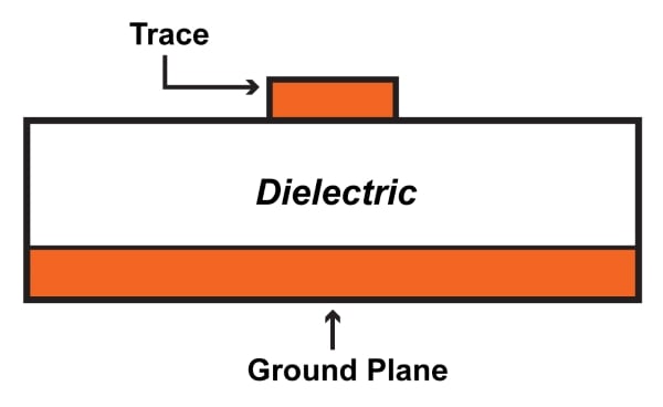
According to this app note from Analog Devices, you can create a 50 Ω microstrip as follows: 1-ounce copper, 20-mil-wide trace, 10-mil separation between trace and ground plane (assuming FR-4 dielectric).
Before we move on, let’s be clear that not every high-frequency system or component is designed for 50 Ω. Other values could be chosen, and in fact 75 Ω impedance is still common. The characteristic impedance of a coaxial cable is proportional to the natural log of the ratio of the outer diameter (D2) to the inner diameter (D1).
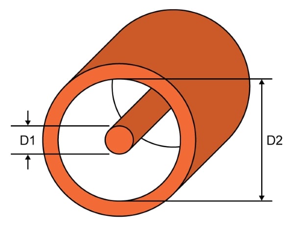
This means that more separation between the inner conductor and outer conductor corresponds to a higher impedance. Greater separation between the two conductors also leads to lower capacitance.
Thus, 75 Ω coax has lower capacitance than 50 Ω coax, and this makes 75 Ω cable more suitable for high-frequency digital signals, which require low capacitance in order to avoid excessive attenuation of the high-frequency content associated with the rapid transitions between logic low and logic high.
Reflection Coefficient
Considering how important impedance matching is in RF design, we shouldn’t be surprised to find that there is a specific parameter used to express the quality of a match. It is called the reflection coefficient; the symbol is Γ (the Greek capital letter gamma). It is the ratio of the complex amplitude of the reflected wave to the complex amplitude of the incident wave.
However, the relationship between incident wave and reflected wave is determined by the source (ZS) and load (ZL) impedances, and thus it is possible to define the reflection coefficient in terms of these impedances:
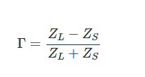
If the “source” in this case is a transmission line, we can change the ZS to Z0.
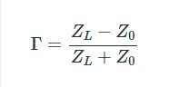
In a typical system, the magnitude of the reflection coefficient is a number between zero and one. Let’s look at three mathematically straightforward situations to help us understand how the reflection coefficient corresponds to actual circuit behavior:
*If the match is perfect (ZL = Z0), the numerator is zero, and thus the reflection coefficient is zero. This makes sense because perfect matching results in no reflection.
*If the load impedance is zero (i.e., a short circuit), the magnitude of the reflection coefficient becomes Z0 divided by Z0. Thus we again have |Γ| = 1, which makes sense because a short circuit also corresponds to a complete discontinuity that cannot absorb any of the incident wave energy.
VSWR
Another parameter used to describe impedance matching is the voltage standing wave ratio (VSWR). It is defined as follows:
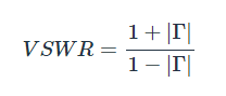
VSWR approaches impedance matching from the perspective of the resulting standing wave. It conveys the ratio of the highest standing-wave amplitude to the lowest standing-wave amplitude. This video can help you visualize the relationship between impedance mismatch and the amplitude characteristics of the standing wave, and the following diagram conveys standing-wave amplitude characteristics for three different reflection coefficients.
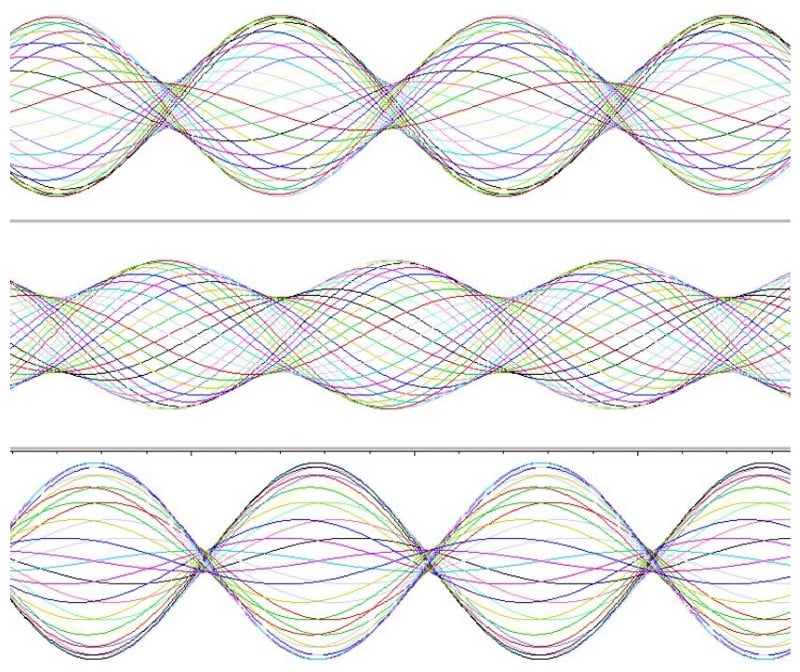
More impedance mismatch leads to a greater difference between the highest-amplitude and lowest-amplitude locations along the standing wave. Image used courtesy of the Interferometrist.
VSWR is commonly expressed as a ratio. A perfect match would be 1:1, meaning that the peak amplitude of the signal is always the same (i.e., there is no standing wave). A ratio of 2:1 indicates that reflections have resulted in a standing wave with a maximum amplitude that is twice as large as its minimum amplitude.
Summary
*The use of a standardized impedance makes RF design much more practical and efficient.
*Most RF systems are built around 50 Ω impedance. Some systems use 75 Ω; this latter value is more appropriate for high-speed digital signals.
*The quality of an impedance match can be expressed mathematically by the reflection coefficient (Γ). A perfect match corresponds to Γ = 0, and a complete discontinuity (in which all the energy is reflected) corresponds to Γ = 1.
*Another way of quantifying the quality of an impedance match is the voltage standing wave ratio (VSWR).
