
Products Category
- FM Transmitter
- 0-50w 50w-1000w 2kw-10kw 10kw+
- TV Transmitter
- 0-50w 50-1kw 2kw-10kw
- FM Antenna
- TV Antenna
- Antenna Accessory
- Cable Connector Power Splitter Dummy Load
- RF Transistor
- Power Supply
- Audio Equipments
- DTV Front End Equipment
- Link System
- STL system Microwave Link system
- FM Radio
- Power Meter
- Other Products
- Special for Coronavirus
Products Tags
Fmuser Sites
- es.fmuser.net
- it.fmuser.net
- fr.fmuser.net
- de.fmuser.net
- af.fmuser.net ->Afrikaans
- sq.fmuser.net ->Albanian
- ar.fmuser.net ->Arabic
- hy.fmuser.net ->Armenian
- az.fmuser.net ->Azerbaijani
- eu.fmuser.net ->Basque
- be.fmuser.net ->Belarusian
- bg.fmuser.net ->Bulgarian
- ca.fmuser.net ->Catalan
- zh-CN.fmuser.net ->Chinese (Simplified)
- zh-TW.fmuser.net ->Chinese (Traditional)
- hr.fmuser.net ->Croatian
- cs.fmuser.net ->Czech
- da.fmuser.net ->Danish
- nl.fmuser.net ->Dutch
- et.fmuser.net ->Estonian
- tl.fmuser.net ->Filipino
- fi.fmuser.net ->Finnish
- fr.fmuser.net ->French
- gl.fmuser.net ->Galician
- ka.fmuser.net ->Georgian
- de.fmuser.net ->German
- el.fmuser.net ->Greek
- ht.fmuser.net ->Haitian Creole
- iw.fmuser.net ->Hebrew
- hi.fmuser.net ->Hindi
- hu.fmuser.net ->Hungarian
- is.fmuser.net ->Icelandic
- id.fmuser.net ->Indonesian
- ga.fmuser.net ->Irish
- it.fmuser.net ->Italian
- ja.fmuser.net ->Japanese
- ko.fmuser.net ->Korean
- lv.fmuser.net ->Latvian
- lt.fmuser.net ->Lithuanian
- mk.fmuser.net ->Macedonian
- ms.fmuser.net ->Malay
- mt.fmuser.net ->Maltese
- no.fmuser.net ->Norwegian
- fa.fmuser.net ->Persian
- pl.fmuser.net ->Polish
- pt.fmuser.net ->Portuguese
- ro.fmuser.net ->Romanian
- ru.fmuser.net ->Russian
- sr.fmuser.net ->Serbian
- sk.fmuser.net ->Slovak
- sl.fmuser.net ->Slovenian
- es.fmuser.net ->Spanish
- sw.fmuser.net ->Swahili
- sv.fmuser.net ->Swedish
- th.fmuser.net ->Thai
- tr.fmuser.net ->Turkish
- uk.fmuser.net ->Ukrainian
- ur.fmuser.net ->Urdu
- vi.fmuser.net ->Vietnamese
- cy.fmuser.net ->Welsh
- yi.fmuser.net ->Yiddish
What is Transistor Biasing and Its Types
Date:2021/10/18 21:55:58 Hits:
Transistors are developed in the year 1947 by the physicists of America named John Bardeen. Before the use of transistors, vacuum tubes used for the purpose to control electronic signals. But the complexity of designing vacuum tubes, more amount of power consumption paved the way for the inception of transistors in modern electronics. The transistors are one of the most frequently used semiconductors utilized in the applications of switching and amplification. To make the transistor function convincingly it must possess certain conditions to operate. The establishment of the operating points will be based on the selection of bias and load resistors. Transistors are designed to operate in various modes among which active mode is preferred for amplification. To enter into various modes of operation transistor biasing is done.What is Transistor Biasing?To achieve the desired switching or the amplification effect a transistor must be supplied with the control amounts of voltages and currents through it. This type of technique is known as transistor biasing. If the transistor is not biased appropriately, it may lead to the poor amplification of the signals resulting in the gain being very low. Hence to obtain an intended outcome biasing plays a major role. Types of Transistor BiasingThe most commonly preferred methods for biasing of transistors areBase resistorCollector to baseBiasing with a collector-feedback resistorVoltage-dividerAbove all the methods follow the same principle to obtain the required amounts of base and collector currents from VCC in the signal zero conditions.Base ResistorThe terminal base of the transistor is connected with a high value of the base resistor.The transistor used in the circuit is of N-P-N type so that the other end of the resistor will be connected to the positive side of the supply.Through VCC required amount of zero signal currents at the base is supplied which will be flowing through the base resistor.This makes the junction base-emitter to be forward biased and the terminal base will be positive in comparison to the emitter terminal.By the selection of the proper values of the base resistor, the required amounts of currents at the base and collector are made to pass.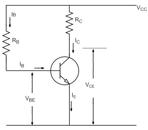 Base Resistor Transistor Biasing The value of the base resistor can be calculated by applying KVLRB = VCC – VBE/ IBDue to the fixed value of VCC and selectively used IB the value of RB can be easily found. Hence, this method can also be referred to as a fixed bias method.AdvantagesCircuit design and calculation are simple.Due to the absence of the resistor at the junction of the base-emitter, there is no chance of occurrence of the loading effect.DisadvantagesDue to the development of heat, the stabilization criterion of the circuit gets degraded.As the value of the stability factor gets high results to thermal runaway.Collector-Base BiasingThis circuit consists of a base resistor that is fed back to the terminal collector instead of VCC. In this way, this circuit is slightly different from the method of the base resistor.
 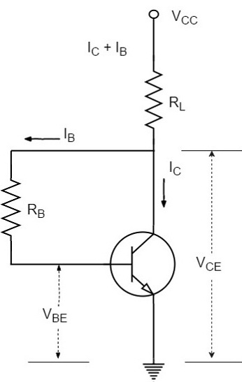 Collector Base Transistor BiasingFrom VCC, the current supplied flows through RL then it reaches the resistor present at the base. This indicates that voltage is shared among the base and collector terminals.If the current at the collector tends to increase the voltage at the load resistor gets increased. This results in an increase in the value of the voltage at the collector-emitter terminal and the current at the base get reduced.AdvantageThe change of Q-point is less when compared to the base bias method.DisadvantagesIf the RL gets short-circuited the value of stability becomes large.The negative path of feedback followed makes the voltage gain smaller.Transistor Biasing with Collector-Feedback ResistorThis method has a resistor at the base such that one end of it is connected to the terminal base whereas the other end will be connected to the collector. The value of the zero signal of the current at the base can be determined by the voltage applied at the junction in between the terminals collector and base (VCB) instead of VCC. Due to VCB, the junction at the base-emitter gets forward-biased.
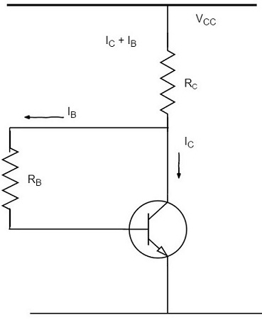 Collector Feedback Resistor AdvantagesThe circuit is very simple in terms of design because fewer resistors are required.Stabilization is provided if there are fewer changes.DisadvantagesNegative feedback is followed by the circuit.Voltage-DividerAmong the existing methods, this type of bias is the widely preferred one. It consists of two resistorsR1 and R2. This circuit of biasing is beneficial in terms of providing stabilization due to the resistor present at the emitter. The drop of voltage at the resistor R2 makes the junction of the base-emitter to operate in forwarding bias.
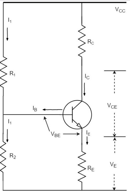 Voltage Divider BiasLet us assume the value of current flows through the resistor R1 is I1. As the current at the base is small the current flow through the resistor R2 is the same as that of R1 that is I1.AdvantageMore than one type of voltage divider circuit can be incorporated by making use of this bias.DisadvantagesThe signals tend to get mixed while using this bias in the circuits.Please refer to this link to know more about transistor biasing MCQsFor the proper functioning biasing of the transistors is a must. In the integrated circuits, the arrangements of biasing circuits are made to achieve the desired stability. Can you describe where the voltage dividing circuit is used practically?
Leave a message
Message List
Comments Loading...
