
Products Category
- FM Transmitter
- 0-50w 50w-1000w 2kw-10kw 10kw+
- TV Transmitter
- 0-50w 50-1kw 2kw-10kw
- FM Antenna
- TV Antenna
- Antenna Accessory
- Cable Connector Power Splitter Dummy Load
- RF Transistor
- Power Supply
- Audio Equipments
- DTV Front End Equipment
- Link System
- STL system Microwave Link system
- FM Radio
- Power Meter
- Other Products
- Special for Coronavirus
Products Tags
Fmuser Sites
- es.fmuser.net
- it.fmuser.net
- fr.fmuser.net
- de.fmuser.net
- af.fmuser.net ->Afrikaans
- sq.fmuser.net ->Albanian
- ar.fmuser.net ->Arabic
- hy.fmuser.net ->Armenian
- az.fmuser.net ->Azerbaijani
- eu.fmuser.net ->Basque
- be.fmuser.net ->Belarusian
- bg.fmuser.net ->Bulgarian
- ca.fmuser.net ->Catalan
- zh-CN.fmuser.net ->Chinese (Simplified)
- zh-TW.fmuser.net ->Chinese (Traditional)
- hr.fmuser.net ->Croatian
- cs.fmuser.net ->Czech
- da.fmuser.net ->Danish
- nl.fmuser.net ->Dutch
- et.fmuser.net ->Estonian
- tl.fmuser.net ->Filipino
- fi.fmuser.net ->Finnish
- fr.fmuser.net ->French
- gl.fmuser.net ->Galician
- ka.fmuser.net ->Georgian
- de.fmuser.net ->German
- el.fmuser.net ->Greek
- ht.fmuser.net ->Haitian Creole
- iw.fmuser.net ->Hebrew
- hi.fmuser.net ->Hindi
- hu.fmuser.net ->Hungarian
- is.fmuser.net ->Icelandic
- id.fmuser.net ->Indonesian
- ga.fmuser.net ->Irish
- it.fmuser.net ->Italian
- ja.fmuser.net ->Japanese
- ko.fmuser.net ->Korean
- lv.fmuser.net ->Latvian
- lt.fmuser.net ->Lithuanian
- mk.fmuser.net ->Macedonian
- ms.fmuser.net ->Malay
- mt.fmuser.net ->Maltese
- no.fmuser.net ->Norwegian
- fa.fmuser.net ->Persian
- pl.fmuser.net ->Polish
- pt.fmuser.net ->Portuguese
- ro.fmuser.net ->Romanian
- ru.fmuser.net ->Russian
- sr.fmuser.net ->Serbian
- sk.fmuser.net ->Slovak
- sl.fmuser.net ->Slovenian
- es.fmuser.net ->Spanish
- sw.fmuser.net ->Swahili
- sv.fmuser.net ->Swedish
- th.fmuser.net ->Thai
- tr.fmuser.net ->Turkish
- uk.fmuser.net ->Ukrainian
- ur.fmuser.net ->Urdu
- vi.fmuser.net ->Vietnamese
- cy.fmuser.net ->Welsh
- yi.fmuser.net ->Yiddish
What is Transformer Coupled Amplifier & Its Working
Date:2021/10/18 21:55:58 Hits:
In multi-stage amplifiers, coupling devices are used to connect different stages of transistor circuits in cascade. When the output of the first stage is connected to the input of the second stage through a coupling/coupled device, then it is referred to as a coupled amplifier. The coupling devices would be a transformer or resistor or capacitor. Based on these devices, there are different types of coupling amplifiers/coupled amplifiers such as Direct-coupling amplifier, RC coupled amplifier, Impedance coupling amplifier, and Transformer coupled amplifier. To overcome the drawbacks of RC coupled amplifiers like high impedance at the output, low impedance at the input, reduced resistance at the load, and reduced voltage gain, a transformer-coupled amplifier is introduced. Here is a brief note in the Transformer-coupled amplifier.What is the Transformer Coupled Amplifier?In multi-stage amplifier circuits, when the output of the first stage is connected to the input of the second stage in cascade through the transformer, then it is called a Transformer Coupled Amplifier. Here Transformer acts as a coupled amplifier. It has a high impedance at the input, a low impedance at the output, a higher voltage gain, higher efficiency, and increased effective load resistance. It is applicable when the load is low and mainly used for power amplification. The turn ratio of a transformer can be utilized for matching impedance with the load. This type of coupling can be used in high-frequency amplifier circuits in the range of Radio Frequency and Intermediate frequencyTransformer Coupled Amplifier Circuit DiagramWhen the output of one stage is connected to the input of another stage through a coupled transformer, then it is called a transformer-coupled amplifier. The circuit diagram of the transformer-coupled amplifier is shown below.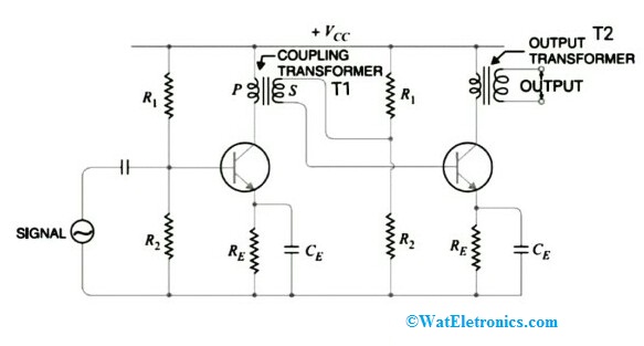 Transformer Coupled Amplifier The coupling transformer T1 is connected between the output of the first stage and the input of the second stage. The collector of the transistor in the first stage is connected to the primary winding of T1 while the secondary winding of T1 is between potential divider R1 and the transistor base in the second stage. Instead of resistor and capacitor, a transformer is used in a transformer-coupled amplifier circuit to achieve high voltage gain and efficiency. Similarly, multiple stages can be formed by the coupling of the transformer.R1, R2, and resistor Re are the potential dividers used for biasing and stabilization purposes. The low reactance path is provided by the by-pass capacitor Ce at the emitter junction of the second stage to the output signal of the first stage. Whereas the coupling capacitor Cc is used to connect these two stages by isolating DC interference from one stage to another stage and also controls the operation. The input capacitor Cin in the first stage allows the AC signal to the base of the transistor.Transformer Coupled Amplifier WorkingWhen Resistor-capacitor is used as a coupling device, the effective load resistance could decrease due to the high output impedance of the first stage would come in parallel with the low input impedance of the second stage. So, a transformer is used to overcome this problem in the coupling of multi-stage amplifiers.The AC input signal applied in the first stage flows through the input capacitor to the base of the transistor by eliminating DC components in the signal. This input signal gets amplified by the transistor in the first stage and it is collected by the primary winding of the transformer T1. Here T1 transformer is used for coupling two stages. The signal, which is amplified in the first stage is fed to the input of the second stage through the secondary winding of T1. Due to the matching property of coupled transformer T1 like matching of impedance property, the low resistance of the load of one stage can be reflected as high load resistance to the previous stage. The voltage of the amplified signal at the primary winding can be converted in accordance with the turns ratio of the secondary winding of T1. This method provides better impedance matching properties, used for power amplification. The output of the circuit has low DC resistance, higher efficiency, higher voltage gain, high input impedance, and low output impedance. The output of the coupling transformer can be referred to as the final output because of its impedance matching properties.Note: The primary winding of T1 acts as a load on the first stage of the transistor while the secondary winding of T1 is for impedance matching for the next stage transistor. The capacitors resonance and increases the selectivity for a range of frequencies that is to be amplified.Consider N1 and N2 are the turns ratio of the transformerZ1 and Z2 are the impedances of primary and secondary windingsThen the relation between primary winding impedance and secondary winding impedance is given by, Z2 = Z1 * (N2/N1)^2Frequency Response of Transformer Coupled AmplifierThe frequency response of the transformer-coupled amplifier is shown below. The frequency response is drawn between voltage gain in dB and frequency in Hz.
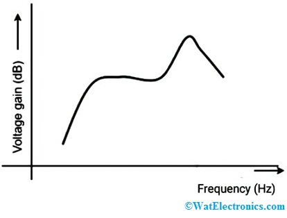 Frequency Response of AmplifierFor a small range of frequencies, the gain of the amplifier is constant. We can get the output voltage, which is equal to the multiplication of the collector current and the reactance of the primary winding of coupling transformer T1. The frequency response characteristics are drawn between the voltage gain (dB) and input frequency.In the lower-frequency range, the reactance of primary winding starts reducing, which results in a decreased gain. Whereas at higher frequencies, the bypass condenser (capacitance between the turns of two windings) reduces the voltage at the output and gain. So, the signal cannot be amplified and some distortion is occurred, called frequency distortion.Advantages/DisadvantagesThe advantages of a transformer-coupled amplifier include the following.No loss in signal power at base and collector resistors.Excellent impedance matching properties of the coupling transformer.High voltage gain due to impedance matching.The voltage gain of a perfectly designed single-stage transformer-coupled amplifier is equal to the gain of two stages of the RC coupled amplifier.Operating efficiency is excellent.The disadvantages of a transformer-coupled amplifier include the following.The coupling of transformers is very costly and design bulk at any frequency range.It has a poor frequency response even though the voltage gain is high.During the amplification of signals, frequency distortion is high.The signals at the low-frequency range are less amplified when compared to the signals at the high-frequency range.The coupling transformer makes some noise (hum) in the output.ApplicationsThe applications of the transformer-coupled amplifier include the following.Used in impedance matching applicationsUsed in the amplification of power.Used in devices where maximum power could be transferred to the output. Ex: loudspeakerUsed in high-frequency amplifiers (RF and IF range) such as radio receivers and TV receivers.Please refer to this link to know more about Transformer Question and AnswersThus, this is all about the transformer-coupled amplifier – definition, circuit diagram, working, advantages, disadvantages, and applications. Here is a question for you, “What is the RC coupled amplifier?”
Leave a message
Message List
Comments Loading...
