
Products Category
- FM Transmitter
- 0-50w 50w-1000w 2kw-10kw 10kw+
- TV Transmitter
- 0-50w 50-1kw 2kw-10kw
- FM Antenna
- TV Antenna
- Antenna Accessory
- Cable Connector Power Splitter Dummy Load
- RF Transistor
- Power Supply
- Audio Equipments
- DTV Front End Equipment
- Link System
- STL system Microwave Link system
- FM Radio
- Power Meter
- Other Products
- Special for Coronavirus
Products Tags
Fmuser Sites
- es.fmuser.net
- it.fmuser.net
- fr.fmuser.net
- de.fmuser.net
- af.fmuser.net ->Afrikaans
- sq.fmuser.net ->Albanian
- ar.fmuser.net ->Arabic
- hy.fmuser.net ->Armenian
- az.fmuser.net ->Azerbaijani
- eu.fmuser.net ->Basque
- be.fmuser.net ->Belarusian
- bg.fmuser.net ->Bulgarian
- ca.fmuser.net ->Catalan
- zh-CN.fmuser.net ->Chinese (Simplified)
- zh-TW.fmuser.net ->Chinese (Traditional)
- hr.fmuser.net ->Croatian
- cs.fmuser.net ->Czech
- da.fmuser.net ->Danish
- nl.fmuser.net ->Dutch
- et.fmuser.net ->Estonian
- tl.fmuser.net ->Filipino
- fi.fmuser.net ->Finnish
- fr.fmuser.net ->French
- gl.fmuser.net ->Galician
- ka.fmuser.net ->Georgian
- de.fmuser.net ->German
- el.fmuser.net ->Greek
- ht.fmuser.net ->Haitian Creole
- iw.fmuser.net ->Hebrew
- hi.fmuser.net ->Hindi
- hu.fmuser.net ->Hungarian
- is.fmuser.net ->Icelandic
- id.fmuser.net ->Indonesian
- ga.fmuser.net ->Irish
- it.fmuser.net ->Italian
- ja.fmuser.net ->Japanese
- ko.fmuser.net ->Korean
- lv.fmuser.net ->Latvian
- lt.fmuser.net ->Lithuanian
- mk.fmuser.net ->Macedonian
- ms.fmuser.net ->Malay
- mt.fmuser.net ->Maltese
- no.fmuser.net ->Norwegian
- fa.fmuser.net ->Persian
- pl.fmuser.net ->Polish
- pt.fmuser.net ->Portuguese
- ro.fmuser.net ->Romanian
- ru.fmuser.net ->Russian
- sr.fmuser.net ->Serbian
- sk.fmuser.net ->Slovak
- sl.fmuser.net ->Slovenian
- es.fmuser.net ->Spanish
- sw.fmuser.net ->Swahili
- sv.fmuser.net ->Swedish
- th.fmuser.net ->Thai
- tr.fmuser.net ->Turkish
- uk.fmuser.net ->Ukrainian
- ur.fmuser.net ->Urdu
- vi.fmuser.net ->Vietnamese
- cy.fmuser.net ->Welsh
- yi.fmuser.net ->Yiddish
What is Opto-coupler/opto-Isolator
Date:2021/10/18 21:55:58 Hits:
 What is Opto-coupler/opto-Isolator
Leave a Comment
/ Uncategorized, What is Optocoupler
ContentsOptocoupler/optoisolatorworking principle of OptocouplerSaturation and linear Mode operation of the optocouplerSaturation modeLinear modePhotodiode vs Phototransistor optocouplersWhy use optocouplers in electronics?Applications of optocouplersSome Most Using and Popular Optocoupler ICs are -PC817, 4N35, MOC3021 etc.
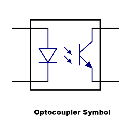
Optocoupler/optoisolator
Opto-coupler is is an electronic component that is used to conduct the electrical signals from one circuit to another circuit without directly connected between them. In other words, an optocoupler is used to transfers electrical signals between two circuits optically. Here both circuit is electrically isolated to each other. Opto-coupler is also called photocoupler, opto-isolator or optical isolator. Optocoupler is mainly used to prevent an electrical collision by the isolate the circuit. This is also used to eliminate unwanted noises.
What is Opto-coupler/opto-Isolator
Leave a Comment
/ Uncategorized, What is Optocoupler
ContentsOptocoupler/optoisolatorworking principle of OptocouplerSaturation and linear Mode operation of the optocouplerSaturation modeLinear modePhotodiode vs Phototransistor optocouplersWhy use optocouplers in electronics?Applications of optocouplersSome Most Using and Popular Optocoupler ICs are -PC817, 4N35, MOC3021 etc.
Optocoupler/optoisolator
Opto-coupler is is an electronic component that is used to conduct the electrical signals from one circuit to another circuit without directly connected between them. In other words, an optocoupler is used to transfers electrical signals between two circuits optically. Here both circuit is electrically isolated to each other. Opto-coupler is also called photocoupler, opto-isolator or optical isolator. Optocoupler is mainly used to prevent an electrical collision by the isolate the circuit. This is also used to eliminate unwanted noises.

 working principle of Optocoupler
An optocoupler consists a Transmitter as IR LED and a Receiver as photosensitive component. when light emitted by an LED and that light hits on the photosensor (Photodiode, Phototransistor, PhotoTriac) then the photosensor starts to flow the current. in this system, the Input Light is proportional to the current at the output.
working principle of Optocoupler
An optocoupler consists a Transmitter as IR LED and a Receiver as photosensitive component. when light emitted by an LED and that light hits on the photosensor (Photodiode, Phototransistor, PhotoTriac) then the photosensor starts to flow the current. in this system, the Input Light is proportional to the current at the output.
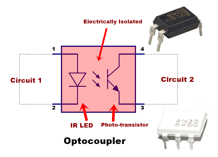
 This is the internal circuit mechanism of an optocoupler. The left side is a led connected through pin 1 and pin 2. And the right side is a phototransistor, this phototransistor is sensitive to light. When the power is given to led, the led emits the light and that light falls on the BASE of the phototransistor, After falling light on the base of the phototransistor this will activate and the output circuit connected with the transistor can be controlled. Here the input circuit connected only with the LED pins of the optocoupler, Output circuit connected with the phototransistor. Both input and output circuit is fully Electrically isolated.
 There is non-conductive material and space is transparent between LED and Photo-transistor. The electrical isolation is very high generally 10KV or higher. Opto-Triac (photo-Triac) is also used at the place of Photo-transistor in optocoupler for direct AC supply controlling at the output.
Optoucpler IC uses an LED optically coupled to a phototransistor, photodiode, or Photo TRIAC in a single package
Optocoupler is commonly used where A computer system or any digital system needs to control or drive a motor or control the high voltage devices. Here computer system circuit and Motor controlling device is fully electrically isolated, there is no interference of electrical signal.
If we need to connect a 220v AC Motor that controlled by a microcontroller or Arduino etc. In this case, we cannot directly connect both. Then there is optocoupler is used. Microcontroller output is directly connected with the input of LED of the optocoupler, and the Phototransistor is connected with the output component like Relay or Triac for 220v Ac connection with the Motor.
In SMPS or any power supply circuit optocoupler may use to detecting the varying DC sample voltage of output and give feedback to input to control the power supply with the maintain the complete electrical isolation between input and output circuit.
Saturation and linear Mode operation of the optocoupler
Saturation mode
In saturation mode LED will ON or OFF so, the output transistor is fully off or fully ON, which means conducting or non-conducting mode. This mode is used where needs to protect the microcontroller pins from the high voltage of the output circuit. For example in motor drive using a microcontroller, the motor needs high current and high voltage. The motor will ON or OFF completely in this mode.
Linear mode
In this mode, LED will get a pulse of signal with a variation. Illumination of LED is varied or controlled with a sample of voltage or signal, then the phototransistor also provides variable conduction to the output. This can be used in a switched-mode power supply (SMPS) or controlling different circuitry where error detection at the output is required.
Photodiode vs Phototransistor optocouplers
photodiode Optocouplers are better than phototransistor optocoupler in a linear relationship between the current and the light. Although phototransistor optocoupler can pass the analog audio signals at wide frequencies by varying the LED beam that goes to the BASE of the phototransistor. The transistor output varies to amplifying as the light beam gets on its BASE. But some distortion may occur at the high frequencies.
Input light and output current relationship of photodiode optocoupler is good in most audio and some digital signals even though the output signal amplitude of photodiode is very less than output provided by the phototransistor.
There is non-conductive material and space is transparent between LED and Photo-transistor. The electrical isolation is very high generally 10KV or higher. Opto-Triac (photo-Triac) is also used at the place of Photo-transistor in optocoupler for direct AC supply controlling at the output.
Optoucpler IC uses an LED optically coupled to a phototransistor, photodiode, or Photo TRIAC in a single package
Optocoupler is commonly used where A computer system or any digital system needs to control or drive a motor or control the high voltage devices. Here computer system circuit and Motor controlling device is fully electrically isolated, there is no interference of electrical signal.
If we need to connect a 220v AC Motor that controlled by a microcontroller or Arduino etc. In this case, we cannot directly connect both. Then there is optocoupler is used. Microcontroller output is directly connected with the input of LED of the optocoupler, and the Phototransistor is connected with the output component like Relay or Triac for 220v Ac connection with the Motor.
In SMPS or any power supply circuit optocoupler may use to detecting the varying DC sample voltage of output and give feedback to input to control the power supply with the maintain the complete electrical isolation between input and output circuit.
Saturation and linear Mode operation of the optocoupler
Saturation mode
In saturation mode LED will ON or OFF so, the output transistor is fully off or fully ON, which means conducting or non-conducting mode. This mode is used where needs to protect the microcontroller pins from the high voltage of the output circuit. For example in motor drive using a microcontroller, the motor needs high current and high voltage. The motor will ON or OFF completely in this mode.
Linear mode
In this mode, LED will get a pulse of signal with a variation. Illumination of LED is varied or controlled with a sample of voltage or signal, then the phototransistor also provides variable conduction to the output. This can be used in a switched-mode power supply (SMPS) or controlling different circuitry where error detection at the output is required.
Photodiode vs Phototransistor optocouplers
photodiode Optocouplers are better than phototransistor optocoupler in a linear relationship between the current and the light. Although phototransistor optocoupler can pass the analog audio signals at wide frequencies by varying the LED beam that goes to the BASE of the phototransistor. The transistor output varies to amplifying as the light beam gets on its BASE. But some distortion may occur at the high frequencies.
Input light and output current relationship of photodiode optocoupler is good in most audio and some digital signals even though the output signal amplitude of photodiode is very less than output provided by the phototransistor.
 Why use optocouplers in electronics?
There are various types of circuits in digital communication systems, power supply systems,s, and other hardware systems designed using the optocouplers by engineers because it makes high sensitive, for protection, most convenient fast switching and highly responsive with a digital signal etc.
Applications of optocouplers
There are the following main uses of the optocoupler
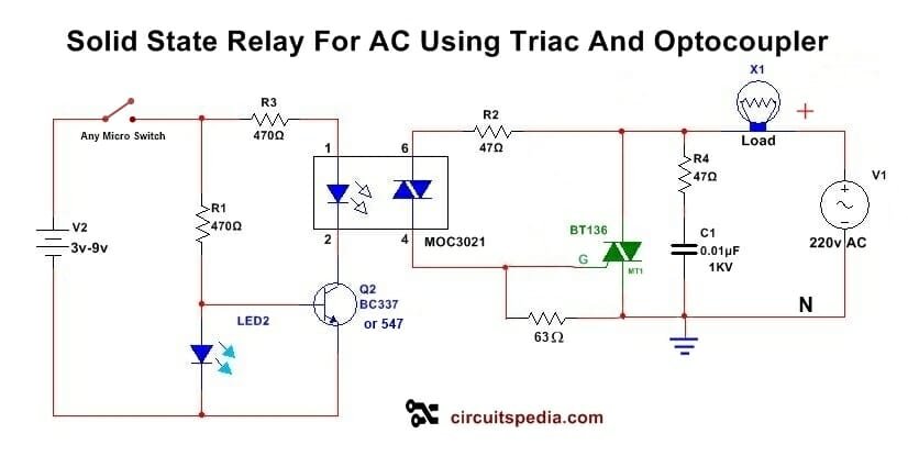
Allow you to use small digital signals to control larger AC voltages.- Solid State Relay is the best example of this. In this, you can switch ON or Switch OFF A 220V AC Load by using 5V DC operated signal supply.
Why use optocouplers in electronics?
There are various types of circuits in digital communication systems, power supply systems,s, and other hardware systems designed using the optocouplers by engineers because it makes high sensitive, for protection, most convenient fast switching and highly responsive with a digital signal etc.
Applications of optocouplers
There are the following main uses of the optocoupler
Allow you to use small digital signals to control larger AC voltages.- Solid State Relay is the best example of this. In this, you can switch ON or Switch OFF A 220V AC Load by using 5V DC operated signal supply.
 Protection from the highly sensitive circuit from a high voltage circuit and–
If you need to drive a high voltage motor using the command with a microcontroller then the optocoupler will provide switching system with the full electrically isolated connection between motor and microcontroller output.
protection from high voltage spikes –
optocoupler is also used as a fuse with advanced features than a fuse. In a circuit, optocoupler is used to switching a system using a digital signal or using a very low voltage, but if there is spikes of voltage or surge current occurs then the whole output circuit will be non-affected because the optocoupler got damaged only and stops the passes the current to next portion.
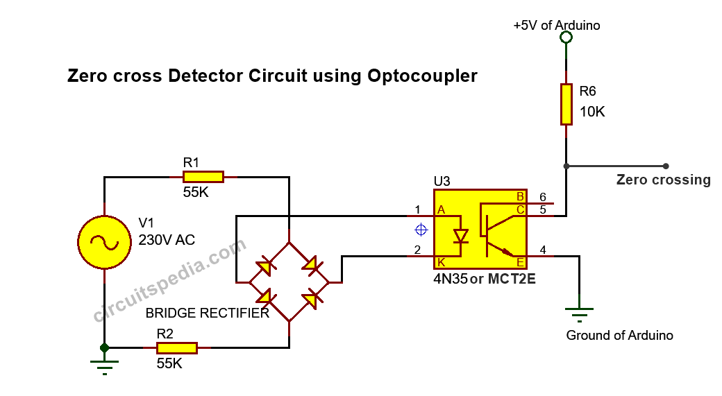
Using optocouplers for sensing zero crossing of AC sources-
by the response time is very fast (nanoseconds), On and off very fastly of the optocoupler, it is widely used to detect the zero-cross of ac power mains by using a rectifier. and by using this digital signal can be found for waveform changing as we required.
Protection from the highly sensitive circuit from a high voltage circuit and–
If you need to drive a high voltage motor using the command with a microcontroller then the optocoupler will provide switching system with the full electrically isolated connection between motor and microcontroller output.
protection from high voltage spikes –
optocoupler is also used as a fuse with advanced features than a fuse. In a circuit, optocoupler is used to switching a system using a digital signal or using a very low voltage, but if there is spikes of voltage or surge current occurs then the whole output circuit will be non-affected because the optocoupler got damaged only and stops the passes the current to next portion.
Using optocouplers for sensing zero crossing of AC sources-
by the response time is very fast (nanoseconds), On and off very fastly of the optocoupler, it is widely used to detect the zero-cross of ac power mains by using a rectifier. and by using this digital signal can be found for waveform changing as we required.
 Also uses to Remove electrical noise from signals.
—————————————————————–
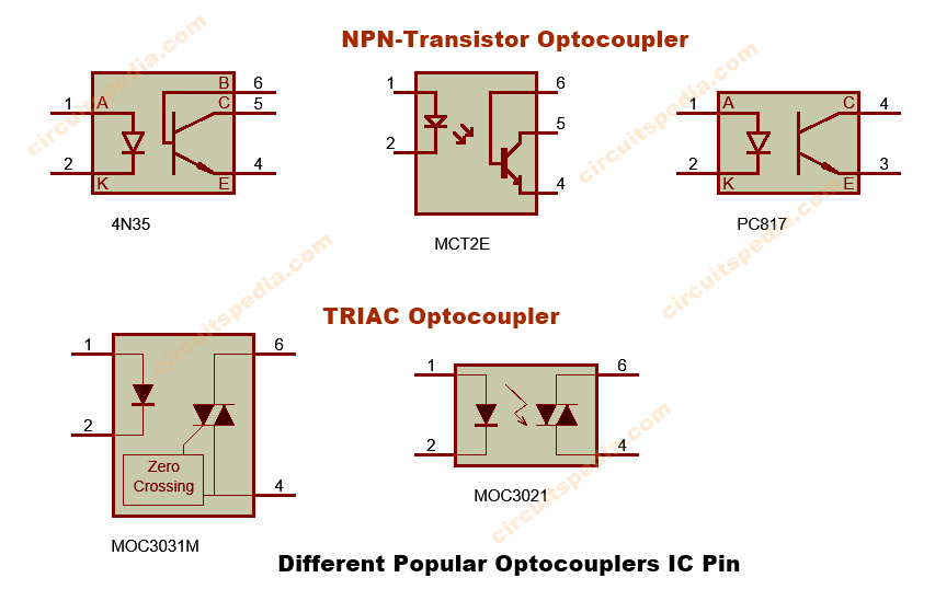
Some Most Using and Popular Optocoupler ICs are -PC817, 4N35, MOC3021 etc.
Also uses to Remove electrical noise from signals.
—————————————————————–
Some Most Using and Popular Optocoupler ICs are -PC817, 4N35, MOC3021 etc.
 Also Read
How capacitor block dc current
Solid State Relay With Triac And Optocoupler
Automatic Light Activated Bulb Switch Controller
Zener diode working
How does a Relay Work,
Also Read
How capacitor block dc current
Solid State Relay With Triac And Optocoupler
Automatic Light Activated Bulb Switch Controller
Zener diode working
How does a Relay Work, Automatic DC FAN controller circuit,
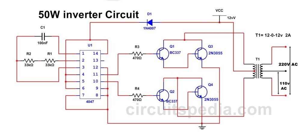 220v 50W Low Power Inverter Circuit,
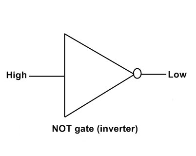 What is NOT gate (Inverter),
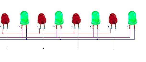 Simple LED Flasher Circuit with 555 timer,
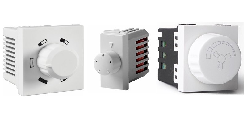 Fan Regulator/AC dimmer,
 Overvoltage Protection AutoCut OFF Using 741
Leave a message
Message List
Comments Loading...
