
Products Category
- FM Transmitter
- 0-50w 50w-1000w 2kw-10kw 10kw+
- TV Transmitter
- 0-50w 50-1kw 2kw-10kw
- FM Antenna
- TV Antenna
- Antenna Accessory
- Cable Connector Power Splitter Dummy Load
- RF Transistor
- Power Supply
- Audio Equipments
- DTV Front End Equipment
- Link System
- STL system Microwave Link system
- FM Radio
- Power Meter
- Other Products
- Special for Coronavirus
Products Tags
Fmuser Sites
- es.fmuser.net
- it.fmuser.net
- fr.fmuser.net
- de.fmuser.net
- af.fmuser.net ->Afrikaans
- sq.fmuser.net ->Albanian
- ar.fmuser.net ->Arabic
- hy.fmuser.net ->Armenian
- az.fmuser.net ->Azerbaijani
- eu.fmuser.net ->Basque
- be.fmuser.net ->Belarusian
- bg.fmuser.net ->Bulgarian
- ca.fmuser.net ->Catalan
- zh-CN.fmuser.net ->Chinese (Simplified)
- zh-TW.fmuser.net ->Chinese (Traditional)
- hr.fmuser.net ->Croatian
- cs.fmuser.net ->Czech
- da.fmuser.net ->Danish
- nl.fmuser.net ->Dutch
- et.fmuser.net ->Estonian
- tl.fmuser.net ->Filipino
- fi.fmuser.net ->Finnish
- fr.fmuser.net ->French
- gl.fmuser.net ->Galician
- ka.fmuser.net ->Georgian
- de.fmuser.net ->German
- el.fmuser.net ->Greek
- ht.fmuser.net ->Haitian Creole
- iw.fmuser.net ->Hebrew
- hi.fmuser.net ->Hindi
- hu.fmuser.net ->Hungarian
- is.fmuser.net ->Icelandic
- id.fmuser.net ->Indonesian
- ga.fmuser.net ->Irish
- it.fmuser.net ->Italian
- ja.fmuser.net ->Japanese
- ko.fmuser.net ->Korean
- lv.fmuser.net ->Latvian
- lt.fmuser.net ->Lithuanian
- mk.fmuser.net ->Macedonian
- ms.fmuser.net ->Malay
- mt.fmuser.net ->Maltese
- no.fmuser.net ->Norwegian
- fa.fmuser.net ->Persian
- pl.fmuser.net ->Polish
- pt.fmuser.net ->Portuguese
- ro.fmuser.net ->Romanian
- ru.fmuser.net ->Russian
- sr.fmuser.net ->Serbian
- sk.fmuser.net ->Slovak
- sl.fmuser.net ->Slovenian
- es.fmuser.net ->Spanish
- sw.fmuser.net ->Swahili
- sv.fmuser.net ->Swedish
- th.fmuser.net ->Thai
- tr.fmuser.net ->Turkish
- uk.fmuser.net ->Ukrainian
- ur.fmuser.net ->Urdu
- vi.fmuser.net ->Vietnamese
- cy.fmuser.net ->Welsh
- yi.fmuser.net ->Yiddish
What is VSWR and how to measure VSWR?

"VSWR in antenna theory stands for voltage standing wave ratio, also known as standing wave ratio (SWR). VSWR is a measurement of the standing wave level on a feeder line. RF engineers know that a very important issue when studying feeder/transmission lines is Standing wave, standing wave represents the power that the load does not accept and reflects back along the transmission line or feeder, while the standing wave ratio is a function of the reflection coefficient, which describes the power reflected by the antenna. ----- FMUSER"
Although standing waves and VSWR are very important, often the VSWR theory and calculations can mask a view of what is actually happening. Fortunately, it is possible to gain a good view of the topic, without delving too deeply into VSWR theory.
4) VSWR vs SWR
5) How VSWR affects performance
When looking at systems that include transmission lines it is necessary to understand that sources, transmission lines / feeders and loads all have a characteristic impedance. 50Ω is a very common standard for RF applications although other impedances may occasionally be seen in some systems.
In order to obtain the maximum power transfer from the source to the transmission line, or the transmission line to the load, be it a resistor, an input to another system, or an antenna, the impedance levels must match.
In other words for a 50Ω system the source or signal generator must have a source impedance of 50Ω, the transmission line must be 50Ω and so must the load.

See Also: >>What is VSWR and Return Loss?
Issues arise when power is transferred into the transmission line or feeder and it travels towards the load. If there is a mismatch, i.e. the load impedance does not match that of the transmission line, then it is not possible for all the power to be transferred.
As power cannot disappear, the power that is not transferred into the load has to go somewhere and there it travels back along the transmission line back towards the source.

When this happens the voltages and currents of the forward and reflected waves in the feeder add or subtract at different points along the feeder according to the phases. In this way standing waves are set up.
The way in which the effect occurs can be demonstrated with a length of rope. If one end is left free and the other is moved up an down the wave motion can be seen to move down along the rope. However if one end is fixed a standing wave motion is set up, and points of minimum and maximum vibration can be seen.
See Also: >> How to Use a VSWR Meter
When the load resistance is lower than the feeder impedance voltage and current magnitudes are set up. Here the total current at the load point is higher than that of the perfectly matched line, whereas the voltage is less.

The values of current and voltage along the feeder vary along the feeder. For small values of reflected power the waveform is almost sinusoidal, but for larger values it becomes more like a full wave rectified sine wave. This waveform consists of voltage and current from the forward power plus voltage and current from the reflected power.

See Also: >>Why Do I Need a Transmitter Circuit before An Antenna?
At a distance a quarter of a wavelength from the load the combined voltages reach a maximum value whilst the current is at a minimum. At a distance half a wavelength from the load the voltage and current are the same as at the load.
A similar situation occurs when the load resistance is greater than the feeder impedance however this time the total voltage at the load is higher than the value of the perfectly matched line. The voltage reaches a minimum at a distance a quarter of a wavelength from the load and the current is at a maximum. However at a distance of a half wavelength from the load the voltage and current are the same as at the load.

See Also: >>What's the difference between "dB", "dBm", and "dBi"?
Then when there is an open circuit placed at the end of the line, the standing wave pattern for the feeder is similar to that of the short circuit, but with the voltage and current patterns reversed.

See Also: >>Make this Radio Repeater Circuit at Home
The definition of VSWR provides the basis for all the calculations and formulas.
The voltage standing wave ratio, VSWR is defined as the ratio of the maximum to minimum voltage on a loss-less line.
The resulting ratio is normally expressed as a ratio, e.g. 2:1, 5:1, etc. A perfect match is 1:1 and a complete mismatch, i.e. a short or open circuit is ∞:1.
In practice there is a loss on any feeder or transmission line. To measure the VSWR, forward and reverse power is detected at that point on the system and this is converted to a figure for VSWR. In this way, the VSWR is measured at a particular point and the voltage maxima and minima do not need to be determined along the length of the line.
What are standing waves? A load is connected to the end of the transmission line and the signal flows along it and enters the load. If the load impedance does not match with the transmission line impedance, then part of the travelling wave is reflected back towards the source.
When reflection occurs, these travel back down the transmission line and combine with the incident waves to produce standing waves. It is important to note that the resultant wave appears stationary like and does not propagate like a normal wave and does not transfer energy toward the load. The wave has areas of maximum and minimum amplitude called anti-nodes and nodes respectively.
When connecting the antenna, if a VSWR of 1.5 is produced, then power efficiency is 96%. When a VSWR of 3.0 is produced, then the power efficiency is 75%. In actual use, it is not recommended to exceed a VSWR of 3.
vswr

Formula for VSWR and reflection coefficient
Eq.1 - Reflection coefficient Γ is defined as:
![]()
Zo = The Characteristic impedance of the transmission line in ohms
Calculated values are between -1 ≦ Γ ≦ 1.
#When value is “-1”.
Means 100% reflection occurs and no power is transferred to the load. The reflected wave is 180 degrees out of phase (inverted) with the incident wave.
#When value is “1”.
Means 100% reflection occurs and no power is transferred to the load. The reflected wave is in phase with the incident wave.
#When value is “0”.
Means no reflection occurs and all power is transferred to the load. (IDEAL)
Eq.2 - The VSWR or voltage standing wave ratio:
Given that ρ will vary from 0 to 1, the calculated values for VSWR will be from 1 through to infinity.
The ideal case is when ρ is 0, giving a VSWR of 1 or a 1:1 ratio.
With open circuit
This is an open circuit condition with no antenna connected. It means that ZL is infinite and the terms Zo will disappear in Eq.1, leaving Γ=1 (100% reflection) and ρ=1.
No power is transferred and VSWR will be infinite.
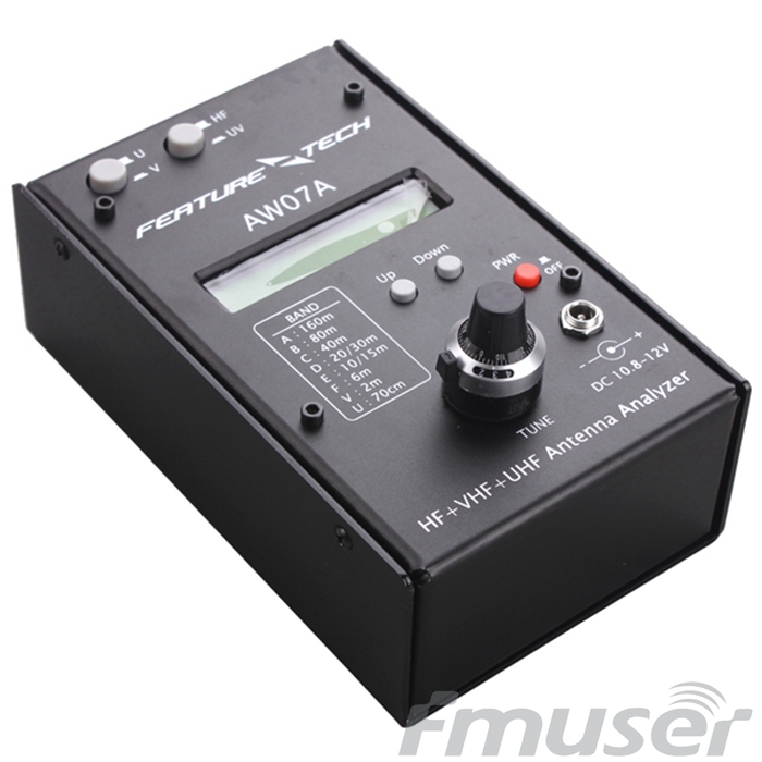
1.5-490Mhz SWR HF/VHF/UHF Antenna Analyzer AW07A
0
With shortcut circuit
Imagine the end of the cable has a short circuit. It means ZL is 0 and the Eq.1 will calculate Γ=-1 and ρ=1.
No power is transferred and VSWR is infinite.With correctly matched antenna.
When a correctly matched antenna is connected, then all energy is transferred to the antenna and is converted to radiation. ZL is 50 ohms and Eq.1 will calculate Γ to be zero. Thus VSWR will be exactly 1.
With incorrectly matched antenna.
When an incorrectly matched antenna is connected, the impedance will no longer be 50 ohms and an impedance mismatch occurs and part of the energy is reflected back. The amount of energy reflected depends on the level of the mismatch and so VSWR will be a value above 1.
When using cable of incorrect characteristic impedance.
The cable / transmission line used to connect the antenna to the transmitter will need to be the correct characteristic impedance Zo. Typically, coaxial cables are 50ohms (75ohms for televisions and satellite) and their values will be printed on the cables themselves. The amount of energy reflected depends on the level of the mismatch and so VSWR will be a value above 1.

Instructions on how to use
- Please enter the values into the light and dark yellow boxes, then push ENTER key.
1. Confirm your cable characteristic impedance and enter into the box.
2. Confirm the load impedance, reflection coefficient, VSWR etc. and press ENTER to calculate.
3. If complete reflection occurs, then POWER REFLECT [%] shows 100% and Output Power graph shows 0%.
Look carefully at where it says D=0. Both waves become “in phase” (both circles moving together) or “Out of phase” (both circles moving in opposite direction) depending on the value of the reflection coefficient.
4. The output power can be calculated by subtracting Mismatch Loss (in dB) from Input Power (dBm) to give output power (dBm)
The terms VSWR and SWR are often seen in the literature about standing waves in RF systems, and many ask about the difference.
● SWR: SWR stands for standing wave ratio. It describes the voltage and current standing waves that appear on the line. It is a generic description for both current and voltage standing waves. It is often used in association with meters used to detect the standing wave ratio. Both current and voltage rise and fall by the same proportion for a given mismatch.
● VSWR: The VSWR or voltage standing wave ratio applies specifically to the voltage standing waves that are set up on a feeder or transmission line. As it is easier to detect the voltage standing waves, and in many instances voltages are more important in terms of device breakdown, the term VSWR is often used, especially within RF design areas.
The term power standing waves is also seen some times. However this is a complete fallacy as the forward and reflected power are constant (assuming no feeder losses) and the power does not rise and fall in the same way as the voltage and current standing waveforms which are the summation of both forward and reflected elements.
See Also:>>What is VSWR and Return Loss?
5) How VSWR affects performance
There are several ways in which VSWR affects the performance of a transmitter system, or any system that may use RF and matched impedances.
Although the term VSWR is normally used, both the voltage and current standing waves can cause issues. Some of the affects are detailed below:
1. Transmitter power amplifiers can be damaged: The increased levels of voltage and current seen on the feeder as a result of the standing waves, can damage the output transistors of the transmitter. Semiconductor devices are very reliable if operated within their specified limits, but the voltage and current standing waves on the feeder can cause catastrophic damage if they cause the devise to operate outside their limits.
2. PA Protection reduces output power: In view of the very real danger of high SWR levels causing damage to the power amplifier, many transmitters incorporate protection circuitry which reduces the output from the transmitter as the SWR rises. This means that a poor match between the feeder and antenna will result in a high SWR which causes the output to be reduced and hence a significant loss in transmitted power.
3. High voltage and current levels can damage feeder: It is possible that the high voltage and current levels caused by the high standing wave ratio can cause damage to a feeder. Although in most cases feeders will be operated well within their limits and the doubling of voltage and current should be able to be accommodated, there are some circumstances when damage can be caused. The current maxima can cause excessive local heating which could distort or melt the plastics used, and the high voltages have been known to cause arcing in some circumstances.
4. Delays caused by reflections can cause distortion: When a signal is reflected by mismatch, it is reflected back towards the source, and can then be reflected back again towards the antenna. A delay is introduced equal to twice the transmission time of the signal along the feeder. If data is being transmitted this can cause inter-symbol interference, and in another example where analogue television was being transmitted, a “ghost” image was seen.
5. Reduction in signal compared to perfectly match system: Interestingly the loss in signal level caused by a poor VSWR is not nearly as great as some may imagine. Any signal reflected by the load, is reflected back to the transmitter and as matching at the transmitter can enable the signal to be reflected back to the antenna again, the losses incurred are fundamentally those introduced by the feeder.
If you want to purchase any FM/TV euipments for broadcasting, please feel free to contact us by Email: [email protected].?


