Products Category
- FM Transmitter
- 0-50w 50w-1000w 2kw-10kw 10kw+
- TV Transmitter
- 0-50w 50-1kw 2kw-10kw
- FM Antenna
- TV Antenna
- Antenna Accessory
- Cable Connector Power Splitter Dummy Load
- RF Transistor
- Power Supply
- Audio Equipments
- DTV Front End Equipment
- Link System
- STL system Microwave Link system
- FM Radio
- Power Meter
- Other Products
- Special for Coronavirus
Products Tags
Fmuser Sites
- es.fmuser.net
- it.fmuser.net
- fr.fmuser.net
- de.fmuser.net
- af.fmuser.net ->Afrikaans
- sq.fmuser.net ->Albanian
- ar.fmuser.net ->Arabic
- hy.fmuser.net ->Armenian
- az.fmuser.net ->Azerbaijani
- eu.fmuser.net ->Basque
- be.fmuser.net ->Belarusian
- bg.fmuser.net ->Bulgarian
- ca.fmuser.net ->Catalan
- zh-CN.fmuser.net ->Chinese (Simplified)
- zh-TW.fmuser.net ->Chinese (Traditional)
- hr.fmuser.net ->Croatian
- cs.fmuser.net ->Czech
- da.fmuser.net ->Danish
- nl.fmuser.net ->Dutch
- et.fmuser.net ->Estonian
- tl.fmuser.net ->Filipino
- fi.fmuser.net ->Finnish
- fr.fmuser.net ->French
- gl.fmuser.net ->Galician
- ka.fmuser.net ->Georgian
- de.fmuser.net ->German
- el.fmuser.net ->Greek
- ht.fmuser.net ->Haitian Creole
- iw.fmuser.net ->Hebrew
- hi.fmuser.net ->Hindi
- hu.fmuser.net ->Hungarian
- is.fmuser.net ->Icelandic
- id.fmuser.net ->Indonesian
- ga.fmuser.net ->Irish
- it.fmuser.net ->Italian
- ja.fmuser.net ->Japanese
- ko.fmuser.net ->Korean
- lv.fmuser.net ->Latvian
- lt.fmuser.net ->Lithuanian
- mk.fmuser.net ->Macedonian
- ms.fmuser.net ->Malay
- mt.fmuser.net ->Maltese
- no.fmuser.net ->Norwegian
- fa.fmuser.net ->Persian
- pl.fmuser.net ->Polish
- pt.fmuser.net ->Portuguese
- ro.fmuser.net ->Romanian
- ru.fmuser.net ->Russian
- sr.fmuser.net ->Serbian
- sk.fmuser.net ->Slovak
- sl.fmuser.net ->Slovenian
- es.fmuser.net ->Spanish
- sw.fmuser.net ->Swahili
- sv.fmuser.net ->Swedish
- th.fmuser.net ->Thai
- tr.fmuser.net ->Turkish
- uk.fmuser.net ->Ukrainian
- ur.fmuser.net ->Urdu
- vi.fmuser.net ->Vietnamese
- cy.fmuser.net ->Welsh
- yi.fmuser.net ->Yiddish
What is VSWR and Return Loss?

"While it is often necessary to calculate the VSWR or return loss, when undertaking RF design, or maintaining or using RF equipment it can sometimes be useful to convert between return loss, VSWR and voltage reflection coefficient and return Loss (dB) is defined as a ratio of the incoming signal to the same reflected signal as it enters a component. The Return Loss (RL) may also be explained as the difference between the power of a transmitted signal and the power of the signal reflections caused by variations in link and channel impedance. ----- FMUSER"
VSWR (Known as Voltage Standing Wave Ratio), is a measure of how efficiently radio-frequency power is transmitted from a power source, through a transmission line, into a load (for example, from a power amplifier through a transmission line, to an antenna).

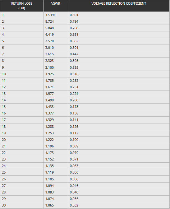
The table showing the conversion between reflected power, VSWR and return loss.
A return loss plot indicates how well the link and channel's impedance matches its rated impedance over a range of frequencies. High return loss values mean a close impedance match, which results in greater differentiation between the powers of transmitted and reflected signals.
When designing or building an electronic circuit, using radio frequency elements the return loss is of great importance as are the voltage standing wave ratio, and reflection coefficient for the signal. This can be of great importance when using or designing RF equipment.
See Also:>> What is the Difference between AM and FM?
Return Loss (dB) is defined as a ratio of the incoming signal to the same reflected signal as it enters a component. The Return Loss (RL) may also be explained as the difference between the power of a transmitted signal and the power of the signal reflections caused by variations in link and channel impedance.
A return loss plot indicates how well the link and channel's impedance matches its rated impedance over a range of frequencies. High return loss values mean a close impedance match, which results in greater differentiation between the powers of transmitted and reflected signals.


