
Products Category
- FM Transmitter
- 0-50w 50w-1000w 2kw-10kw 10kw+
- TV Transmitter
- 0-50w 50-1kw 2kw-10kw
- FM Antenna
- TV Antenna
- Antenna Accessory
- Cable Connector Power Splitter Dummy Load
- RF Transistor
- Power Supply
- Audio Equipments
- DTV Front End Equipment
- Link System
- STL system Microwave Link system
- FM Radio
- Power Meter
- Other Products
- Special for Coronavirus
Products Tags
Fmuser Sites
- es.fmuser.net
- it.fmuser.net
- fr.fmuser.net
- de.fmuser.net
- af.fmuser.net ->Afrikaans
- sq.fmuser.net ->Albanian
- ar.fmuser.net ->Arabic
- hy.fmuser.net ->Armenian
- az.fmuser.net ->Azerbaijani
- eu.fmuser.net ->Basque
- be.fmuser.net ->Belarusian
- bg.fmuser.net ->Bulgarian
- ca.fmuser.net ->Catalan
- zh-CN.fmuser.net ->Chinese (Simplified)
- zh-TW.fmuser.net ->Chinese (Traditional)
- hr.fmuser.net ->Croatian
- cs.fmuser.net ->Czech
- da.fmuser.net ->Danish
- nl.fmuser.net ->Dutch
- et.fmuser.net ->Estonian
- tl.fmuser.net ->Filipino
- fi.fmuser.net ->Finnish
- fr.fmuser.net ->French
- gl.fmuser.net ->Galician
- ka.fmuser.net ->Georgian
- de.fmuser.net ->German
- el.fmuser.net ->Greek
- ht.fmuser.net ->Haitian Creole
- iw.fmuser.net ->Hebrew
- hi.fmuser.net ->Hindi
- hu.fmuser.net ->Hungarian
- is.fmuser.net ->Icelandic
- id.fmuser.net ->Indonesian
- ga.fmuser.net ->Irish
- it.fmuser.net ->Italian
- ja.fmuser.net ->Japanese
- ko.fmuser.net ->Korean
- lv.fmuser.net ->Latvian
- lt.fmuser.net ->Lithuanian
- mk.fmuser.net ->Macedonian
- ms.fmuser.net ->Malay
- mt.fmuser.net ->Maltese
- no.fmuser.net ->Norwegian
- fa.fmuser.net ->Persian
- pl.fmuser.net ->Polish
- pt.fmuser.net ->Portuguese
- ro.fmuser.net ->Romanian
- ru.fmuser.net ->Russian
- sr.fmuser.net ->Serbian
- sk.fmuser.net ->Slovak
- sl.fmuser.net ->Slovenian
- es.fmuser.net ->Spanish
- sw.fmuser.net ->Swahili
- sv.fmuser.net ->Swedish
- th.fmuser.net ->Thai
- tr.fmuser.net ->Turkish
- uk.fmuser.net ->Ukrainian
- ur.fmuser.net ->Urdu
- vi.fmuser.net ->Vietnamese
- cy.fmuser.net ->Welsh
- yi.fmuser.net ->Yiddish
What is Wave Analyzer : Working & Its Applications
Date:2021/10/18 21:55:58 Hits:
In electronics and communications, the periodic signal is represented in the form of DC component and some sinusoidal harmonics. It is necessary to analyze the harmonics present in the signal. So, wave analyzers are used to measure the amplitude of the harmonics in the domain of frequency with the help of tuned filters and voltmeters. The wave analyzer can be tuned to analyze the frequency of the harmonic component of the signal whose amplitude is to be measured. Here is a complete description of the Wave Analyzer.Wave Analyzer DefinitionAn electronic instrument that analyzes the signal or wave by measuring the amplitude of the frequency components or harmonics is called a Wave Analyzer. It is also known as signal analyzer or carrier frequency voltmeters or frequency-selective voltmeters, or selective level voltmeters. This instrument uses a set of filters for tuning and voltmeters to analyze the signal in the frequency domain. The wave analyzers are available in the RF range (low) and 50 MHz below range and also runs through AF range with high-frequency resolution. Block DiagramThe wave analyzer block diagram is shown below. It contains a primary detector, full-wave rectifier, and PMMC galvanometer.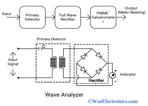 Wave Analyzer Block DiagramPrimary Detector: It is made up of an LC circuit. By adjusting the values of ‘L’ (inductor) and ‘C’, the particular frequency component of the signal is allowed to measure.Full-wave Rectifier: The input AC signal is converted into the DC signal and the average value of the signal is obtainedPMMC Galvanometer: It is used to indicate the value of the signal i.e, the output of the full-wave rectifier.Types of Wave AnalyzerThere are two types of wave analyzers used to analyze the frequency components in the signal. Basic Wave AnalyzerThe basic wave analyzer circuit diagram is shown below. The basic wave analyzer works as a frequency selective voltmeter because it is tuned to a particular frequency component and rejects all other components of the signal, which is to be analyzed. The CRO or a voltmeter is used as an indicator to measure the amplitude. A switch is used to connect the set of tuned filters with the indicator.Principle and WorkingThe basic wave analyzer works on the principle of the frequency-selective voltmeter. It should be tuned to any one frequency component of the signal and all other components are rejected. The particular selected frequency component of the wave/signal is calibrated in the form of amplitude and its value indicated by a voltmeter or CRO.From the circuit, the LC circuit is used as a primary detector to adjust the resonance to measure the desired frequency component of the harmonics of the signal. The average DC value of the input signal is obtained by the full-wave rectifier. The output of the full-wave rectifier is calibrated in the form of peak value and it is indicated by a DC voltmeter.Based upon Frequency RangesBased on the frequency ranges, the wave analyzers are divided into two types. Heterodyne Wave AnalyzerThe electronic instrument that analyzes the periodic signal in the RF range and above MHz ranges, is called heterodyne wave analyzer. It is also known as a superheterodyne wave analyzer. Its working principle is heterodyne (mix) of high IF (intermediate frequency range) with the input signal, which is to be analyzed. The frequency components of the signal are fed to the passband IF amplifier due to the tuning of the local oscillator. The IF amplifier is rectified and applied to the meter circuit to display the output.The block diagram of the heterodyne wave analyzer is shown below.
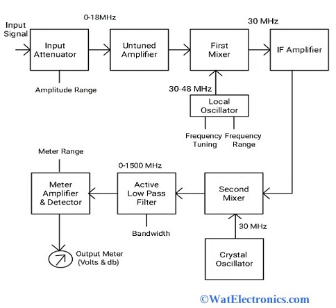 Heterodyne WaveanalyzerThe input RF signal that is to be analyzed is given to an input attenuator to attenuate the amplitude of the signal. The output signal will be in the range of 0-18 MHz.The output of the input attenuator is fed to the untuned amplifier to amplify the RF signal and its output is fed to the first mixer.The signal of the first mixer is heterodyned with the signal from the local oscillator in the frequency range of 30-48MHz. The output of the first mixer will be in the 30MHz frequency range i.e., IF signal. The IF amplifier amplifies the IF signal obtained from the first mixer.This amplified IF signal of 30MHz is heterodyned (mixed) with the Crystal oscillator signal frequency 30MHz in the second mixer. As the frequencies of the signals are the same, the output frequency of the second mixer is 0 Hz.This output signal with 0 Hz is applied to an active low pass filter which has a frequency range of 0-1500MHz.The output of the active LPF is fed to the meter circuit to display the reading of the selected RF signal in the range of volts or decibels.Frequency Selective Wave Analyzer> Principle: The frequency selective wave analyzer is one of the types of wave analyzer works on the principle of the frequency-selective voltmeter. It is operated to measure the frequency in the audio range of 20 Hz – 20 kHz. It uses a narrow-pass band filter and it is tuned to the desired frequency components to measure. The block diagram of the frequency selective wave analyzer is shown below. The frequency distortion is very low and bandwidth is also low nearly 1% of the selected frequency.The AF input signal that is to be analyzed is given to an input attenuator. The signal contains maximum amplitude and it is attenuated by the input attenuator. It works as a range multiplier because a high range of amplitude of the signal is measured.
 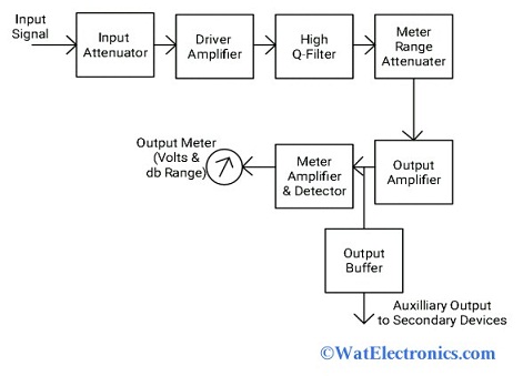 Frequency Selective Wave AnalyzerThe output of the input attenuator is amplified by the driver amplifier and its output is fed to the high-Q filter section.The high Q-filter section selected the particular frequency component and rejects the remaining unwanted frequencies of the signal. It contains two RC sections, two amplifier filters, connected in cascade. By varying the value of the capacitor, the frequency range can be changed. By varying the value of the resistor, the desired frequency can be changed within the desired range.The output of the High Q-filter is fed to the meter range attenuator to select the AF input signal. The AF input signal is attenuated by a meter range attenuator. The output of the meter range attenuator is amplified by the output amplifier. The output buffer drives the AF signal to the output devices such as counters, recorders, etc. The meter circuits display the reading output of the AF signal in the range of volts and decibels.Applications of Wave AnalyzerThe applications of wave analyzer areMeasures the harmonic distortion of the signal.Desired frequency components of the signal can be selected to analyze the signalUsed in harmonics analyzation whose signal is to be analyzed.Measuring the amplitude of the selected frequency component in the signal.Used to analyze the DC component in the periodic signalUsed to reduce sound and vibration produced by the electrical machines in the industries.Used to measure the amplitude of the signal along with noise and interfering signals.Used as a harmonic distortion analyzerUsed as an automatic frequency controller.Used in electrical measurementsThus, this is all about wave analyzers- definition, block diagram, types, and applications. The purpose of the wave analyzer is to analyze the periodic signal in the RF and AF range. A suitable wave analyzer should be selected based on the frequency range of the signal. Here is a question for you “What is Harmonic distortion analyzer?”
Leave a message
Message List
Comments Loading...
