
Products Category
- FM Transmitter
- 0-50w 50w-1000w 2kw-10kw 10kw+
- TV Transmitter
- 0-50w 50-1kw 2kw-10kw
- FM Antenna
- TV Antenna
- Antenna Accessory
- Cable Connector Power Splitter Dummy Load
- RF Transistor
- Power Supply
- Audio Equipments
- DTV Front End Equipment
- Link System
- STL system Microwave Link system
- FM Radio
- Power Meter
- Other Products
- Special for Coronavirus
Products Tags
Fmuser Sites
- es.fmuser.net
- it.fmuser.net
- fr.fmuser.net
- de.fmuser.net
- af.fmuser.net ->Afrikaans
- sq.fmuser.net ->Albanian
- ar.fmuser.net ->Arabic
- hy.fmuser.net ->Armenian
- az.fmuser.net ->Azerbaijani
- eu.fmuser.net ->Basque
- be.fmuser.net ->Belarusian
- bg.fmuser.net ->Bulgarian
- ca.fmuser.net ->Catalan
- zh-CN.fmuser.net ->Chinese (Simplified)
- zh-TW.fmuser.net ->Chinese (Traditional)
- hr.fmuser.net ->Croatian
- cs.fmuser.net ->Czech
- da.fmuser.net ->Danish
- nl.fmuser.net ->Dutch
- et.fmuser.net ->Estonian
- tl.fmuser.net ->Filipino
- fi.fmuser.net ->Finnish
- fr.fmuser.net ->French
- gl.fmuser.net ->Galician
- ka.fmuser.net ->Georgian
- de.fmuser.net ->German
- el.fmuser.net ->Greek
- ht.fmuser.net ->Haitian Creole
- iw.fmuser.net ->Hebrew
- hi.fmuser.net ->Hindi
- hu.fmuser.net ->Hungarian
- is.fmuser.net ->Icelandic
- id.fmuser.net ->Indonesian
- ga.fmuser.net ->Irish
- it.fmuser.net ->Italian
- ja.fmuser.net ->Japanese
- ko.fmuser.net ->Korean
- lv.fmuser.net ->Latvian
- lt.fmuser.net ->Lithuanian
- mk.fmuser.net ->Macedonian
- ms.fmuser.net ->Malay
- mt.fmuser.net ->Maltese
- no.fmuser.net ->Norwegian
- fa.fmuser.net ->Persian
- pl.fmuser.net ->Polish
- pt.fmuser.net ->Portuguese
- ro.fmuser.net ->Romanian
- ru.fmuser.net ->Russian
- sr.fmuser.net ->Serbian
- sk.fmuser.net ->Slovak
- sl.fmuser.net ->Slovenian
- es.fmuser.net ->Spanish
- sw.fmuser.net ->Swahili
- sv.fmuser.net ->Swedish
- th.fmuser.net ->Thai
- tr.fmuser.net ->Turkish
- uk.fmuser.net ->Ukrainian
- ur.fmuser.net ->Urdu
- vi.fmuser.net ->Vietnamese
- cy.fmuser.net ->Welsh
- yi.fmuser.net ->Yiddish
What is UJT Relaxation Oscillator & Its Working
Date:2021/10/18 21:55:58 Hits:
A three-terminal semiconductor device like UJT (uni-junction transistor) exhibits different characteristics like switching and negative resistance to using as a relaxation oscillator within phase control applications. This type of transistor can also be used in timing, trigger generator, and gate pulse applications. Similar to diodes, the construction of UJT can be done by using separate P-type & N-type semiconductor materials to form a single PN junction in the main N-type conducting channel of the device. As compared to FETs & BJTs, the switching characteristic of this transistor is different. So it cannot be used for amplifying a signal but it can be used as a switching transistor to ON/OFF. This article discusses an overview of the UJT relaxation oscillator, circuit, and its working.What is UJT Relaxation Oscillator?Generally, a relaxation oscillator is a non-linear oscillator and the main function of this is to produce non-sinusoidal output waveforms like a square wave, triangular wave which triggers power control devices like TRIACs and SCRs. 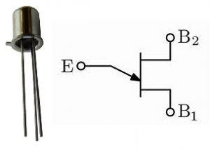 Uni Junction TransistorThese waveforms are also called non-sinusoidal signal generators. This type of oscillator works in such a way that it produces oscillations through charging the capacitor & rapidly discharging it once achieving a fixed threshold voltage.Similarly, a UJT relaxation oscillator is one kind of RC oscillator where the uni-junction transistor works as an active element. As the name suggests, the timing interval can be set up through the capacitor charging & it can be ceased through the quick discharge of a similar capacitor. UJT Relaxation Oscillator Circuit DiagramThe basic UJT relaxation oscillator circuit diagram is shown below: This circuit can be built with a unijunction transistor (UJT) & a capacitor. Here the charging and discharging of this capacitor can be done through the resistors like R1 & R2 where the R1 resistor charges the capacitor and the R2 resistor discharges the capacitor. Here, VBB in the circuit is an external voltage supply.Let us discuss how a UJT relaxation oscillator generates a non-sinusoidal output signal. Once the external voltage like VBB is given to the circuit, the capacitor connected to the circuit will start charging through the R1 resistor. Once the capacitor gets charged then the voltage across the capacitor will be increased till a peak voltage is attained which is indicated with ‘Vp’.
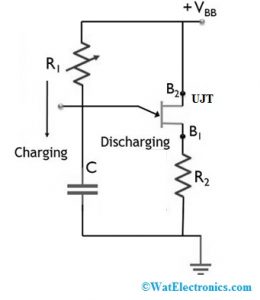 UJT Relaxation Oscillator CircuitOnce the capacitor voltage reaches Vp, then the transistor will be turned ON in the circuit. When the transistor activates, then the capacitor will start discharging through the R2 resistor in the circuit. So, the discharging current which is flowing through the R2 resistor will generate a voltage spike. For the UJT relaxation oscillator, the following voltage waveforms will represent the R2 resistor and capacitor. At the discharging time of a capacitor, the voltage across the capacitor will reduce to VV. When the cut-off condition is achieved, then the capacitor again will start charging thus the repetitive cycle of capacitor takes place. The charging and discharging of the repetitive cycle for the capacitor will generate a sawtooth waveform.We can notice that once UJT is turned off, then the output voltage will be zero. The applied voltage at this specific interval will charge the capacitor thus output voltage is zero. Because of this reason, the relaxing condition of the oscillator is called the relaxation oscillator. Consequently, the oscillator’s oscillation frequency mainly depends on the charging & discharging of the capacitor.UJT Relaxation Oscillator Frequency FormulaThe frequency of the UJT relaxation oscillator can be determined by the Resistor & capacitor. So, the frequency of this oscillator can be determined through the following equation.F = 1/ (RC ln(1/(1-η))In the above equation, ‘η’ = Intrinsic standoff ratioln = stand for natural logarithm.The oscillation frequency for this oscillator can be given by F = 1/R1C. It is extremely significant to identify that the R1 resistor should include values that must be in a suitable range to oscillate to the circuit.The resistor values can be obtained by using these formulasR1 max = (Vs-Vp)/IpR1 min = (Vs-Vv)/IvWhere,Vs = the value of power supply voltageVp = Obtained value based on the parameters of UJTIp, Vv & Iv = specification of manufacturerUJT CharacteristicsThe unijunction transistor characteristics can be explained through the following threeCutoffNegative Resistance RegionSaturationCutoffThis is the region where the UJT doesn’t obtain adequate voltage to activate. The voltage which is applied hasn’t achieved the triggering voltage, so the transistor will be deactivated.Negative Resistance RegionOnce the UJT gets the triggering voltage, then it will be turned ON. If the applied voltage increases, then it will reach peak voltage. When the current increases, then the voltage can be reduced from peak to valley point.SaturationIn this region, if the voltage applied to the emitter terminal increases, then the voltage & current flow will be increased.AdvantagesThe advantages of UJT include the following.Not expensiveSwitching response is goodNegative resistance characteristicsUJT has good electrical and temperature characteristics.It uses less triggering current valueIt absorbs less powerIt absorbs less powerTriggering voltage stableDisadvantagesThe disadvantages of UJT include the following.Its incapability to generate suitable amplification.It is not applicable for linear amplifiersNot used for extremely high frequency but works with simply less to moderate frequencyIt has the property of negative impedance so it is not suitable to employ in some circuits.UJT Relaxation Oscillator ApplicationsThe applications of UJT include the following.UJT transistors are used in any digital circuit to generate internal clock signaling. These are also used in oscilloscopes, TV receivers & thyristor triggering circuits.UJT is used as a speed control circuit by generating a set of signals by controlling and activating the thyristor.These transistors are used to control the speed of the universal motor with the combination of TRIAC and SCR.UJTs are used in pulse generator circuits as well as synchronized oscillators which work at low to moderate frequencies.UJTs are used in both current regulated & voltage regulated with SMPS circuits.These transistors are used for building relaxation oscillator circuits.Relaxation oscillators are used in oscilloscopes, TV receivers, stroboscopes, electronic camera flashes, in digital circuits for generating clock signals.Please refer to this link to know more about Oscillators MCQsThus, this is all about an overview of the UJT relaxation oscillator, circuit, and its working. This transistor is one kind of trigger device that is used in conjunction with thyristor power-control devices. Here is a question for you, what are the different types of transistors?
Leave a message
Message List
Comments Loading...
