
Products Category
- FM Transmitter
- 0-50w 50w-1000w 2kw-10kw 10kw+
- TV Transmitter
- 0-50w 50-1kw 2kw-10kw
- FM Antenna
- TV Antenna
- Antenna Accessory
- Cable Connector Power Splitter Dummy Load
- RF Transistor
- Power Supply
- Audio Equipments
- DTV Front End Equipment
- Link System
- STL system Microwave Link system
- FM Radio
- Power Meter
- Other Products
- Special for Coronavirus
Products Tags
Fmuser Sites
- es.fmuser.net
- it.fmuser.net
- fr.fmuser.net
- de.fmuser.net
- af.fmuser.net ->Afrikaans
- sq.fmuser.net ->Albanian
- ar.fmuser.net ->Arabic
- hy.fmuser.net ->Armenian
- az.fmuser.net ->Azerbaijani
- eu.fmuser.net ->Basque
- be.fmuser.net ->Belarusian
- bg.fmuser.net ->Bulgarian
- ca.fmuser.net ->Catalan
- zh-CN.fmuser.net ->Chinese (Simplified)
- zh-TW.fmuser.net ->Chinese (Traditional)
- hr.fmuser.net ->Croatian
- cs.fmuser.net ->Czech
- da.fmuser.net ->Danish
- nl.fmuser.net ->Dutch
- et.fmuser.net ->Estonian
- tl.fmuser.net ->Filipino
- fi.fmuser.net ->Finnish
- fr.fmuser.net ->French
- gl.fmuser.net ->Galician
- ka.fmuser.net ->Georgian
- de.fmuser.net ->German
- el.fmuser.net ->Greek
- ht.fmuser.net ->Haitian Creole
- iw.fmuser.net ->Hebrew
- hi.fmuser.net ->Hindi
- hu.fmuser.net ->Hungarian
- is.fmuser.net ->Icelandic
- id.fmuser.net ->Indonesian
- ga.fmuser.net ->Irish
- it.fmuser.net ->Italian
- ja.fmuser.net ->Japanese
- ko.fmuser.net ->Korean
- lv.fmuser.net ->Latvian
- lt.fmuser.net ->Lithuanian
- mk.fmuser.net ->Macedonian
- ms.fmuser.net ->Malay
- mt.fmuser.net ->Maltese
- no.fmuser.net ->Norwegian
- fa.fmuser.net ->Persian
- pl.fmuser.net ->Polish
- pt.fmuser.net ->Portuguese
- ro.fmuser.net ->Romanian
- ru.fmuser.net ->Russian
- sr.fmuser.net ->Serbian
- sk.fmuser.net ->Slovak
- sl.fmuser.net ->Slovenian
- es.fmuser.net ->Spanish
- sw.fmuser.net ->Swahili
- sv.fmuser.net ->Swedish
- th.fmuser.net ->Thai
- tr.fmuser.net ->Turkish
- uk.fmuser.net ->Ukrainian
- ur.fmuser.net ->Urdu
- vi.fmuser.net ->Vietnamese
- cy.fmuser.net ->Welsh
- yi.fmuser.net ->Yiddish
What is Hartley Oscillator : Working and Its Applications
Date:2021/10/18 21:55:58 Hits:
An electronic oscillator in which the oscillator frequency is determined through a tuned circuit consisting of inductors and capacitors is called the Harley oscillator. The invention of the Harley oscillator circuit was done in 1915 by Ralph Hartley, an American engineer. This oscillator is a type of harmonic oscillator. The Hartley Oscillator produces the waves of radio frequencies therefore it is also referred to as radiofrequency oscillators. The tank circuit of the oscillator having a capacitor connected in parallel with two serially connected inductors decides its frequency. In normal LC oscillators, the circuit generates an uncontrollable amplitude of oscillations. Here Hartley oscillator circuit is not like a normal LC circuit, it uses an LC parallel feedback configuration that has a self-tuning base oscillator circuit. This article discusses an overview of what are Heartley oscillator and its working.Hartley Oscillator Circuit and WorkingThe following figure shows the circuit diagram of the Hartley oscillator circuit. It forms the stabilizing network with Re where Re is the emitter resistance and Rc is the collector resistance. R1 AND R2 resistors form voltage divider bias network for the transistor in common- emitter configuration. Here Co is the output decoupling capacitor, Cin is the input decoupling capacitor and Ce is emitter capacitor. Here Ce is also the bypass capacitor as it bypasses the amplified AC signals. Here L1 and L2 and C form the tank circuit. The components in the Hartley Oscillator circuit are similar to the common emitter amplifier circuit. 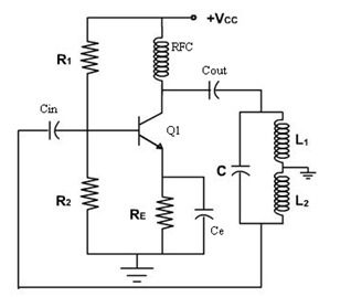 Hartley Oscillator CircuitRFC refers to radio frequency choke which is used in providing the isolation between Ac and DC operation. During high frequencies, choke reactance value is very high, so there it is considered as an open circuit, its reactance for DC condition is zero. So there will be no problem for DC capacitors.When power is switched on, the transistor conducts which increases collector current. Due to this capacitor, C1 starts to charge, after completion of charging in C1, it starts to discharge through the L1 coil. Due to the process of charging and discharging, a series of damped oscillations are produced in the tank circuit. These oscillations produced get coupled to the Q1 base which turns to amplified signal across emitter and collector of the transistor. This voltage present at transistors collector and emitter will be in phase with L1 inductor voltage. As the junction of L1 and L2 are grounded, the voltage across inductor L2 Will be 180 degrees out of phase to the voltage at inductor L1. The voltage at L2 is given as input to the base of Q1 through feedback. We can see clearly that the feedback voltage is 180 degrees out of phase and as the CE configured transistor creates a 180 degrees phase difference. So finally 1 phase difference of 360 degrees is made between input and output voltages. The oscillators will be operated lower than 20KHz when coming to lower frequencies, the inductor value has to be high.Frequency of Hartley OscillatorThe frequency of Hartley Oscillator is given as ƒ = 1/(2π√LT C)where LT = L1 + L2 +2M Here L1 and L2 are the inductances of coil 1 and coil 2. Total cumulative coupled inductance is denoted as Lt and M is the mutual inductance. By considering two windings, mutual inductance can be calculated.When inductor coils are winded on the single-core, then the occurrence of mutual inductance takes place which tends to change in behavior of oscillator circuit. So both L1 and L2 to be winded on single-coreHartley Oscillator Using OP-AMPA Hartley oscillator using an operational amplifier (op-amp) is shown in the figure. The construction of this oscillator using Op-Amp has its own advantages. OP- Amp gain can be easily adjusted by using the input resistance and feedback resistance. Here in the transistorized hartley oscillator, the gain of the op-amp depends on the tank circuit elements L1 and L2 i.e. the gain of the circuit should be equal to or it should be greater than the ration of L1/L2. But in the Op-Amp oscillator, the gain is less dependent on the tank circuit elements so it achieved greater frequency stability.
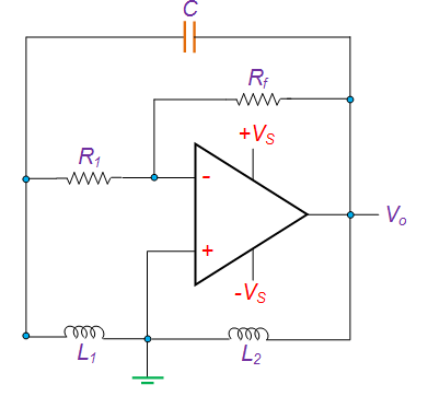 Hartley Oscillator Using OP-AMPThe Op-Amp circuit operation and transistor version of the Hartley oscillator operation are somewhat similar. Feedback circuit generates the sinewave which is coupled with the Op-Amp section. This wave will get stabilized and inverted by the amplifier. In the tank circuit, a variable capacitor is used for varying the frequency of the oscillator by keeping amplitude and feedback ratio constant over a frequency range. The frequency of this oscillator using op-amp is the same as that of the above-discussed oscillator. When mutual inductance exists between two inductors L1 and L2 due to the common core between the coils, the gain becomes Av = (L1+M)/ (L2+M)AdvantagesThe advantages of Hartley oscillator areThe need for components is very less even after including the tapped coil or fixed inductors.Frequency of oscillation can be varied by varying the inductance or by using a variable capacitorA single coil of bare wire can be used instead of using two separate inductive coils L1 and L2.The circuit is very simple and it’s not complex.Sinusoidal oscillations with constant amplitude can be generated in the Hartley oscillator.DisadvantagesThe disadvantages of Hartley oscillator areSometimes distorted sinusoidal signals will get generated due to the presence of harmonics. This is one of the major disadvantages of the Hartley oscillator.The Hartley oscillator can’t be used as a low-frequency oscillator because the size of the inductor and the value of the inductor is large.ApplicationsThe applications of Hartley oscillator is discussed belowThe Hartley oscillator is used as a local oscillator in radio receivers. Due to the reason for a wide range of frequencies, it is a popular oscillator.This oscillator is suitable for oscillations in Radio Frequency (RF) range up to 30MHz.This oscillator used for producing sine wave with the desired frequencyPlease refer to this link to know more Oscillators MCQsThus, this is all about an overview of heartly oscillator, circuit working, advantages, disadvantages, and its applications. Here is a question for you, what are the types of oscillators?
Leave a message
Message List
Comments Loading...
