
Products Category
- FM Transmitter
- 0-50w 50w-1000w 2kw-10kw 10kw+
- TV Transmitter
- 0-50w 50-1kw 2kw-10kw
- FM Antenna
- TV Antenna
- Antenna Accessory
- Cable Connector Power Splitter Dummy Load
- RF Transistor
- Power Supply
- Audio Equipments
- DTV Front End Equipment
- Link System
- STL system Microwave Link system
- FM Radio
- Power Meter
- Other Products
- Special for Coronavirus
Products Tags
Fmuser Sites
- es.fmuser.net
- it.fmuser.net
- fr.fmuser.net
- de.fmuser.net
- af.fmuser.net ->Afrikaans
- sq.fmuser.net ->Albanian
- ar.fmuser.net ->Arabic
- hy.fmuser.net ->Armenian
- az.fmuser.net ->Azerbaijani
- eu.fmuser.net ->Basque
- be.fmuser.net ->Belarusian
- bg.fmuser.net ->Bulgarian
- ca.fmuser.net ->Catalan
- zh-CN.fmuser.net ->Chinese (Simplified)
- zh-TW.fmuser.net ->Chinese (Traditional)
- hr.fmuser.net ->Croatian
- cs.fmuser.net ->Czech
- da.fmuser.net ->Danish
- nl.fmuser.net ->Dutch
- et.fmuser.net ->Estonian
- tl.fmuser.net ->Filipino
- fi.fmuser.net ->Finnish
- fr.fmuser.net ->French
- gl.fmuser.net ->Galician
- ka.fmuser.net ->Georgian
- de.fmuser.net ->German
- el.fmuser.net ->Greek
- ht.fmuser.net ->Haitian Creole
- iw.fmuser.net ->Hebrew
- hi.fmuser.net ->Hindi
- hu.fmuser.net ->Hungarian
- is.fmuser.net ->Icelandic
- id.fmuser.net ->Indonesian
- ga.fmuser.net ->Irish
- it.fmuser.net ->Italian
- ja.fmuser.net ->Japanese
- ko.fmuser.net ->Korean
- lv.fmuser.net ->Latvian
- lt.fmuser.net ->Lithuanian
- mk.fmuser.net ->Macedonian
- ms.fmuser.net ->Malay
- mt.fmuser.net ->Maltese
- no.fmuser.net ->Norwegian
- fa.fmuser.net ->Persian
- pl.fmuser.net ->Polish
- pt.fmuser.net ->Portuguese
- ro.fmuser.net ->Romanian
- ru.fmuser.net ->Russian
- sr.fmuser.net ->Serbian
- sk.fmuser.net ->Slovak
- sl.fmuser.net ->Slovenian
- es.fmuser.net ->Spanish
- sw.fmuser.net ->Swahili
- sv.fmuser.net ->Swedish
- th.fmuser.net ->Thai
- tr.fmuser.net ->Turkish
- uk.fmuser.net ->Ukrainian
- ur.fmuser.net ->Urdu
- vi.fmuser.net ->Vietnamese
- cy.fmuser.net ->Welsh
- yi.fmuser.net ->Yiddish
What is Gate Turnoff Thyristor & Its Working
Date:2021/10/18 21:55:58 Hits:
“Thyristor” is a semiconductor device that is popularly used as a switch in power circuits. With alternating layers of P-type and N-type materials, the thyristor is designed as a four-layered structure. It is available as both two-lead and three-lead designs. The three-lead design of the thyristor consists of an anode, a cathode, and a Gate lead. The thyristor usually starts conducting when the gate lead is triggered with the current and once turned ON, the thyristor conducts continuously until the device voltage is reversed or removed. For a long time, this was the only way to turn OFF a thyristor, which made it difficult to apply for direct current applications. Later a newer design was introduced which removed this drawback on the thyristor by implementing an easy way to turn ON and turn OFF the thyristor. This new design was named “Gate Turnoff Thyristor”.What is Gate Turnoff Thyristor?Gate Turnoff Thyristor is also popularly referred to as “GTO”. This is one of the three-lead designs of Thyristor. As the name suggests, GTO is an improved design of thyristor that can be both turned ON and Turned OFF with the application of current trigger to the gate circuit. This feature of Gate Turnoff Thyristor allows the application of devices where DC is used, which was not the case for earlier thyristors. Basics Of Gate Turnoff ThyristorListed below are some of the basics of Gate Turnoff Thyristor:Gate Turnoff Thyristor is a high-power semiconductor Thyristor.These are fully controllable switches that can perform both the turn ON and turn OFF functions.To prevent device destruction during operation, GTO requires additional external circuitry to control the turn ON and turn OFF currents.This device was invented at “General Electric”.GTO is an active semiconductor device.GTO SymbolAs GTO is a three-lead thyristor, it contains Anode-lead, Cathode-lead, and Gate-lead. The symbol of Gate Turnoff Thyristor is very much similar to SCR Thyristor, except for the gate terminal. Gate Turnoff Thyristor is capable of both turning ON and turning OFF of the device. As this function is exhibited at the gate terminal, the gate terminal is represented with a two-way arrow connection that symbolizes this feature of Thyristor. The figure below shows the symbol of Gate Turnoff Thyristor.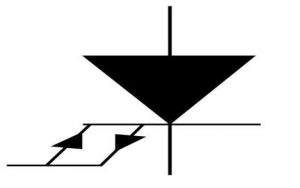 Symbol of Gate Turnoff Thyristor Structure of Gate Turnoff ThyristorGate Turnoff Thyristor has a four-layered P-N-P -P structure. The regions are represented as P+, N-, P, N+. The Anode of the device is connected with a heavily doped P+ layer. The cathode of the device is connected to a heavily doped N+ layer. Gate is also connected to another heavily doped P+ region. The structure of GTO is shown below.
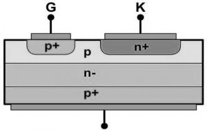 Gate Turnoff Thyristor StructureOperationTo understand the operation of the Gate Turnoff Thyristor, one has to look at both its turn ON and turn OFF mechanism.Turn ON MechanismSimilar to SCR, a GTO can be turned ON by applying a positive pulse with respect to the cathode, to its gate terminal. But this Turn On process of GTO is not as reliable as that of SCR. Turn OFF MechanismTo turn OFF a Gate Turnoff Thyristor, a negative gate pulse with respect to the cathode is applied at the gate terminal. The application on negative pulse evacuates the charge carriers from anode and gate regions.Usually, GTO has the capacity to block reverse voltage. But it has a lower blocking capacity. So, GTO’s are connected in parallel to increase its turning OFF resistance. The GTO that can block the reverse voltage is known as Symmetrical GTO Thyristors, S-GTO. The GTO that cannot block reverse voltage is known as Asymmetrical GTO Thyristors, A-GTO. S-GTO is used as current source inverters. A-GTO is used as voltage source inverters, DC traction choppers.V-I CharacteristicsThe VI characteristics of GTO include the following.Reverse Bias CharacteristicsIn the reverse bias condition, the cathode is positive with respect to the anode. At this point, the N+layer, P-layer junction will be reverse biased as well as N- layer, P+ layer junction. Thus, these two reversed biased junctions will not allow the flow of current from cathode to anode. Consequently, a very minor current flows in the device when in a reverse-biased condition. When a breakdown occurs in this region, a larger current flow occurs.Forward Bias CharacteristicsIn the forward bias condition, the anode is positive with respect to the cathode. Now, both N+, P junction, and N-,P+ junction both are in forward biased condition. Here, the central junction, P,-N gets reverse biased. Due to this only a minor amount of current flows before the breakdown of the junction. At this point, if a positive pulse is applied, a breakdown occurs and the device gets turned ON. After breakdown larger amount of current flows in the circuit. Once the device is turned ON, one has to apply a negative gate pulse to turn OFF GTO. Here, the applied negative gate pulse should be one-third to one-fifth of anode voltage .i.e. 1/3 * anode voltage. This gate rating must also be observed when purchasing the device.
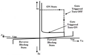 GTO CharacteristicsFor a GateTurnoff Thyristor with V-I ratings of 1600v, 350A turn ON voltage is 3.4 volts. The turn ON time of GTO is 2 microseconds which is much faster than SCR which takes 8 microseconds to turn ON. GTO is ten times faster than SCR. The turn OFF time for GTO is 15 microseconds. GTO can operate at frequencies as high as 1kHz. The Gate current to be applied to turn ON GTO is 2 amperes and for Turn OFF the gate voltage required is 200 Amperes, which is way too high. Due to this a complex circuit design is required at the gate terminal of GTO. There are newer versions of GTO introduced in the market known as Integrated Gate Commutated Thyristors, IGCT, which had an in-built amplifier at the gate terminal, so the device can operate at a lower turn OFF current.ApplicationsThe applications of GTO include the following.GTOs are used in AC drivers, DC choppers, DC circuit breakers, and induction heating systems. These are also applied in high-power inverters and variable-speed motor drives. Nowadays, Gate Turnoff Thyristors are being replaced by Integrated Gate-Commuted Thyristors.To assist in Turn OFF process, Gate Turnoff Thyristor is constructed by connecting a large number of thyristors in parallel. Even after turning ON the device, for better reliability, at least a small amount of gate current has to be retained. Gate Turnoff Thyristor is also provided with a snubber circuit to protect the device from overheating and damage during the turn ON process. To turn OFF a Gate Turnoff Thyristor which current is applied?
Leave a message
Message List
Comments Loading...
