
Products Category
- FM Transmitter
- 0-50w 50w-1000w 2kw-10kw 10kw+
- TV Transmitter
- 0-50w 50-1kw 2kw-10kw
- FM Antenna
- TV Antenna
- Antenna Accessory
- Cable Connector Power Splitter Dummy Load
- RF Transistor
- Power Supply
- Audio Equipments
- DTV Front End Equipment
- Link System
- STL system Microwave Link system
- FM Radio
- Power Meter
- Other Products
- Special for Coronavirus
Products Tags
Fmuser Sites
- es.fmuser.net
- it.fmuser.net
- fr.fmuser.net
- de.fmuser.net
- af.fmuser.net ->Afrikaans
- sq.fmuser.net ->Albanian
- ar.fmuser.net ->Arabic
- hy.fmuser.net ->Armenian
- az.fmuser.net ->Azerbaijani
- eu.fmuser.net ->Basque
- be.fmuser.net ->Belarusian
- bg.fmuser.net ->Bulgarian
- ca.fmuser.net ->Catalan
- zh-CN.fmuser.net ->Chinese (Simplified)
- zh-TW.fmuser.net ->Chinese (Traditional)
- hr.fmuser.net ->Croatian
- cs.fmuser.net ->Czech
- da.fmuser.net ->Danish
- nl.fmuser.net ->Dutch
- et.fmuser.net ->Estonian
- tl.fmuser.net ->Filipino
- fi.fmuser.net ->Finnish
- fr.fmuser.net ->French
- gl.fmuser.net ->Galician
- ka.fmuser.net ->Georgian
- de.fmuser.net ->German
- el.fmuser.net ->Greek
- ht.fmuser.net ->Haitian Creole
- iw.fmuser.net ->Hebrew
- hi.fmuser.net ->Hindi
- hu.fmuser.net ->Hungarian
- is.fmuser.net ->Icelandic
- id.fmuser.net ->Indonesian
- ga.fmuser.net ->Irish
- it.fmuser.net ->Italian
- ja.fmuser.net ->Japanese
- ko.fmuser.net ->Korean
- lv.fmuser.net ->Latvian
- lt.fmuser.net ->Lithuanian
- mk.fmuser.net ->Macedonian
- ms.fmuser.net ->Malay
- mt.fmuser.net ->Maltese
- no.fmuser.net ->Norwegian
- fa.fmuser.net ->Persian
- pl.fmuser.net ->Polish
- pt.fmuser.net ->Portuguese
- ro.fmuser.net ->Romanian
- ru.fmuser.net ->Russian
- sr.fmuser.net ->Serbian
- sk.fmuser.net ->Slovak
- sl.fmuser.net ->Slovenian
- es.fmuser.net ->Spanish
- sw.fmuser.net ->Swahili
- sv.fmuser.net ->Swedish
- th.fmuser.net ->Thai
- tr.fmuser.net ->Turkish
- uk.fmuser.net ->Ukrainian
- ur.fmuser.net ->Urdu
- vi.fmuser.net ->Vietnamese
- cy.fmuser.net ->Welsh
- yi.fmuser.net ->Yiddish
Types of MOSFET – Operation, Working & Applications
Date:2021/10/18 21:55:57 Hits:
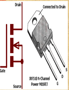 MOSFETThe MOSFET is an important element in embedded system design which is used to control the loads as per the requirement. Many of electronic projects developed using MOSFET such as light intensity control, motor control and max generator applications. The MOSFET is a high voltage controlling device provides some key features for circuit designers in terms of their overall performance. This article provides information about different types of MOSFET applications. MOSFET and Its ApplicationsThe MOSFET (Metal Oxide Semiconductor Field Effect Transistor) transistor is a semiconductor device which is widely used for switching and amplifying electronic signals in the electronic devices.The MOSFET is a three terminal device such as source, gate, and drain. The MOSFET is very far the most common transistor and can be used in both analog and digital ckt.The MOSFET works by varying the width of a channel along which charge carriers flow (holes and electrons). The charge carriers enter the channel from the source and exits through the drain. The channel width is controlled by the voltage on an electrode is called gate which is located between the source and drain. It is insulated from the channel near an extremely thin layer of metal oxide. There is a different type of MOSFET applications which is used as per the requirement.Types of MOSFET DevicesThe MOSFET is classified into two types such as; Depletion mode MOSFETEnhancement mode MOSFETDepletion Mode: When there is zero voltage on the gate terminal, the channel shows its maximum conductance. As the voltage on the gate is negative or positive, then decreases the channel conductivity.
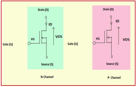 Depletion Mode MOSFETEnhancement ModeWhen there is no voltage on the gate terminal the device does not conduct. More voltage applied on the gate terminal, the device has good conductivity.
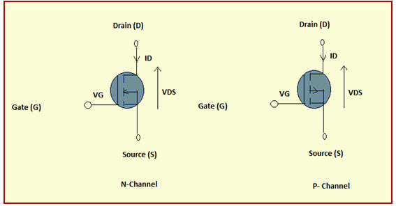 Enhance Mode MOSFET MOSFET Working PrincipleThe working of MOSFET depends upon the metal oxide capacitor (MOS) that is the main part of the MOSFET. The oxide layer presents among the source and drain terminal. It can be set from p-type to n-type by applying positive or negative gate voltages respectively. When apply the positive gate voltage the holes present under the oxide layer with a repulsive force and holes are pushed downward through the substrate. The deflection region populated by the bound negative charges which are allied with the acceptor atoms.
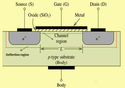 MOSFET Block DiagramP- Channel MOSFETThe P-Channel MOSFET consist negative ions so it works with negative voltages. When we apply the negative voltage to gate, the electrons present under the oxide layer through pushed downward into the substrate with a repulsive force. The deflection region populates by the bound positive charges which are allied with the donor atoms. The negative voltage also attracts holes from p+ source and drain region into the channel region.
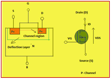 P-Channel MOSFETN- Channel MOSFETWhen we apply the positive gate voltage the holes present under the oxide layer pushed downward into the substrate with a repulsive force. The deflection region is populated by the bound negative charges which are allied with the acceptor atoms. The positive voltage also attracts electrons from the n+ source and drain regions into the channel. Now, if a voltage is applied among the drain and source the current flows freely between the source and drain and the gate voltage controls the electrons in the channel. In place of positive voltage if we apply a negative voltage (hole) channel will be formed under the oxide layer.
 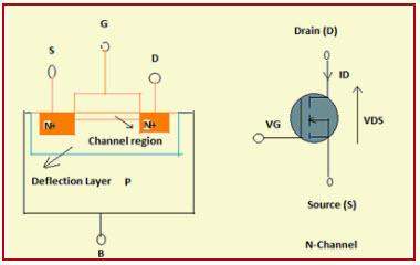 N-Channel MOSFETMOSFET ApplicationsThe applications of the MOSFET used in various electrical and electronic projects which are designed by using various electrical and electronic components. For better understanding of this concept, here we have explained some projects.MOSFET Used as a SwitchIn this circuit, using enhanced mode, a N-channel MOSFET is being used to switch the lamp for ON and OFF. The positive voltage is applied at the gate of the MOSFET and the lamp is ON (VGS =+v) or at the zero voltage level the device turns off (VGS=0). If the resistive load of the lamp was to be replaced by an inductive load and connected to the relay or diode to protect the load. In the above circuit, it is a very simple circuit for switching a resistive load such as LEDs or lamp. But when using MOSFET to switch either inductive load or capacitive load protection is required to contain the MOSFET applications. If we are not giving the protection, then the MOSFET will be damaged. For the MOSFET to operate as an analog switching device, that needs to be switched between its cutoff region where VGS =0 and saturation region where VGS =+v.
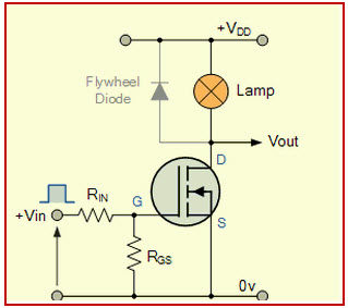 MOSFET As a SwitchAuto Intensity Control of Street Lights using MOSFETNow-a-days most of lights placed on the highways are done through High Intensity Discharge lamps (HID), whose energy consumption is high. Its intensity cannot be controlled according to the requirement, so there is a need to switch on to an alternative method of lighting system, i.e., to use LEDs. This system is built to overcome the present day drawbacks of HID lamps.
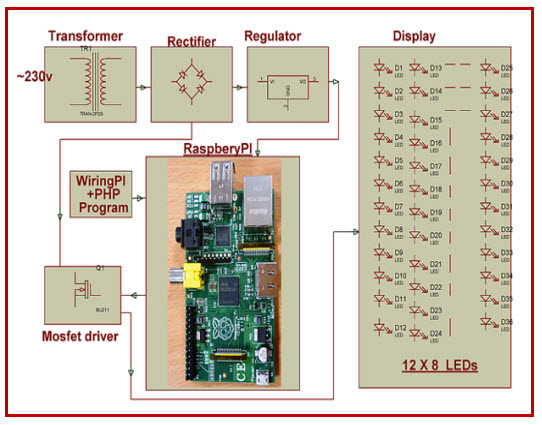 Auto Intensity Control of Street Lights using MOSFETThis project is designed to control the lights automatically on the highways using microprocessor by variants of the clock pulses. In this project, MOSFET plays major role that is used to switch the lamps as per the requirement. The proposed system using a Raspberry Pi board that is a new development board consist a processor to control it. Here we can replace the LEDs in place of HID lamps which are connected to the processor with the help of the MOSFET. The microcontroller release the respective duty cycles, then switch the MOSFET to illuminate the light with bright intensityMarx Generator Based High Voltage Using MOSFETsThe main concept of this project is to develop a circuit that delivers the output approximately triple to that of the input voltage by Marx generator principle. It is designed to generate high-voltage pulses using a number of capacitors in parallel to charge during the on time, and then connected in series to develop a higher voltage during the off period. If the input voltage applied is around 12v volts DC, then the output voltage is around 36 volts DC.
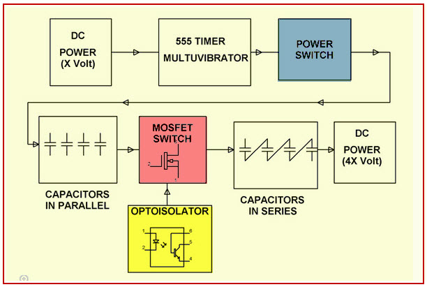 Marx Generator Based High Voltage Using MOSFETsThis system utilizes a 555 timer in astable mode, which delivers the clock pulses to charge the parallel capacitors during on time and the capacitors are brought in a series during the off time through MOSFET switches; and thus, develops a voltage approximately triple to the input voltage but little less, instead of exact 36v due to the voltage drop in the circuit. The output voltage can be measured with the help of the multimeter.EEPROM based Preset Speed Control of BLDC MotorThe speed control of the BLDC motor is very essential in industries as it is important for many applications such as drilling, spinning and elevator systems. This project is enhanced to control the speed of the BLDC motor by varying the duty cycle.
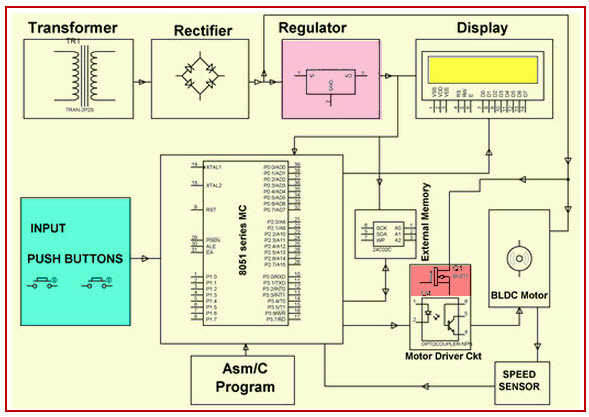 EEPROM based Preset Speed Control of BLDC MotorThe main intention of this project is to operate a BLDC motor at a particular speed with a predefined voltage . Therefore, the motor remains in an operational state or restarted to operate at the same speed as before by using stored data from an EEPROM.The speed control of the DC motor is achieved by varying the duty cycles (PWM Pulses) from the microcontroller as per the program. The microcontroller receives the percentage of duty cycles stored in the EEPROM from inbuilt switch commands and delivers the desired output to switch the driver IC in order to control the speed of the DC motor. If the power supply is interrupted, the EEPROM retains that information to operate the motor at the same speed as before while the power supply was available.LDR Based Power Saver for Intensity Controlled Street LightIn the present system, mostly the lightning-up of highways is done through High Intensity Discharge lamps (HID), whose energy consumption is high and there is no specialized mechanism to turn on the Highway light in the evening and switch off in the morning.
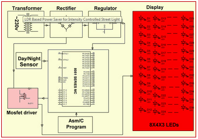 LDR Based Power Saver for Intensity Controlled Street LightIts intensity cannot be controlled according to the requirement, so there is a need to switch to an alternative method of lighting system, i.e., by using LEDs. This system is built to overcome the present day, drawback of HID lamps.This system demonstrates the usage of LEDs (light emitting diodes) as light source and its variable intensity control, according to the requirement. LEDs consume less power and its life is more, as compared to conventional HID lamps.The most important and interesting feature is its intensity that can be controlled according to requirement during non-peak hours, which is not feasible in HID lamps. A light sensing device LDR (Light Dependent Resistance) is used to sense the light. Its resistance reduces drastically according to the daylight, which forms as an input signal to the controller . A cluster of LEDs is used to form a street light. The microcontroller contains programmable instructions that controls the intensity of lights based on the PWM (Pulse width modulation) signals generated.The intensity of light is kept high during the peak hours, and as the traffic on the roads tend to decrease in late nights; the intensity also decreases progressively till morning. Finally the lights get completely shut down at morning 6 am, to resume again at 6pm in the evening. The process thus repeats.SVPWM (Space Vector Pulse Width Modulation)The Space Vector PWM is a sophisticated technique for controlling AC motors by generating a fundamental sine wave that provides a pure voltage to the motor with lower total harmonic distortion. This method overcomes the old technique SPWM to control an AC motor that has high-harmonic distortion due to the asymmetrical nature of the PWM switching characteristics.
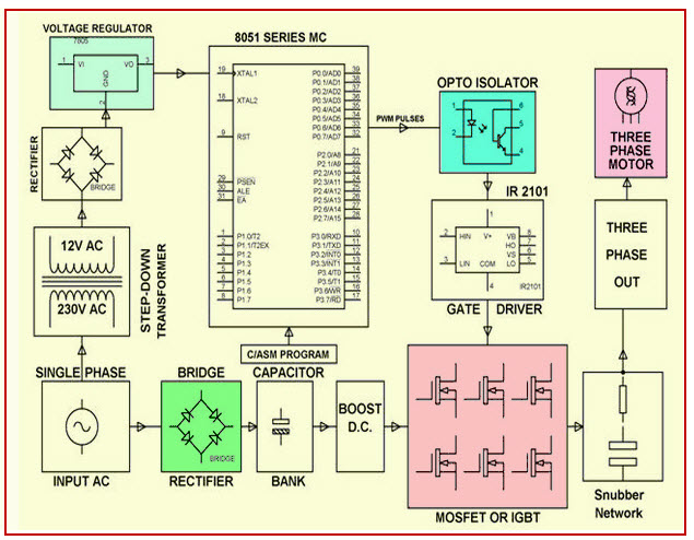 SVPWM (Space Vector Pulse Width Modulation)In this system, DC supply is produced from the single-phase AC after rectification, and then is fed to the 3-phase inverter with 6 numbers of MOSFETs. For each phase, a pair of MOSFETare used, and, therefore, three pairs of MOSFETs are switched at certain intervals of time for producing three-phase supply to control the speed of the motor. This circuit also gives light indication of any fault that occurs in the control circuitPlease refer to this link to know more MOSFET MCQsTherefore, this is all about types of MOSFET applications, Finally, we will conclude that, the MOSFET requires high voltage whereas transistor requires low voltage and current. As compared to a BJT, the driving requirement for the MOSFET is much better.Furthermore, any queries regarding this article you can comment us by commenting in the comment section below.
Prev:Types of MCB
Leave a message
Message List
Comments Loading...
