
Products Category
- FM Transmitter
- 0-50w 50w-1000w 2kw-10kw 10kw+
- TV Transmitter
- 0-50w 50-1kw 2kw-10kw
- FM Antenna
- TV Antenna
- Antenna Accessory
- Cable Connector Power Splitter Dummy Load
- RF Transistor
- Power Supply
- Audio Equipments
- DTV Front End Equipment
- Link System
- STL system Microwave Link system
- FM Radio
- Power Meter
- Other Products
- Special for Coronavirus
Products Tags
Fmuser Sites
- es.fmuser.net
- it.fmuser.net
- fr.fmuser.net
- de.fmuser.net
- af.fmuser.net ->Afrikaans
- sq.fmuser.net ->Albanian
- ar.fmuser.net ->Arabic
- hy.fmuser.net ->Armenian
- az.fmuser.net ->Azerbaijani
- eu.fmuser.net ->Basque
- be.fmuser.net ->Belarusian
- bg.fmuser.net ->Bulgarian
- ca.fmuser.net ->Catalan
- zh-CN.fmuser.net ->Chinese (Simplified)
- zh-TW.fmuser.net ->Chinese (Traditional)
- hr.fmuser.net ->Croatian
- cs.fmuser.net ->Czech
- da.fmuser.net ->Danish
- nl.fmuser.net ->Dutch
- et.fmuser.net ->Estonian
- tl.fmuser.net ->Filipino
- fi.fmuser.net ->Finnish
- fr.fmuser.net ->French
- gl.fmuser.net ->Galician
- ka.fmuser.net ->Georgian
- de.fmuser.net ->German
- el.fmuser.net ->Greek
- ht.fmuser.net ->Haitian Creole
- iw.fmuser.net ->Hebrew
- hi.fmuser.net ->Hindi
- hu.fmuser.net ->Hungarian
- is.fmuser.net ->Icelandic
- id.fmuser.net ->Indonesian
- ga.fmuser.net ->Irish
- it.fmuser.net ->Italian
- ja.fmuser.net ->Japanese
- ko.fmuser.net ->Korean
- lv.fmuser.net ->Latvian
- lt.fmuser.net ->Lithuanian
- mk.fmuser.net ->Macedonian
- ms.fmuser.net ->Malay
- mt.fmuser.net ->Maltese
- no.fmuser.net ->Norwegian
- fa.fmuser.net ->Persian
- pl.fmuser.net ->Polish
- pt.fmuser.net ->Portuguese
- ro.fmuser.net ->Romanian
- ru.fmuser.net ->Russian
- sr.fmuser.net ->Serbian
- sk.fmuser.net ->Slovak
- sl.fmuser.net ->Slovenian
- es.fmuser.net ->Spanish
- sw.fmuser.net ->Swahili
- sv.fmuser.net ->Swedish
- th.fmuser.net ->Thai
- tr.fmuser.net ->Turkish
- uk.fmuser.net ->Ukrainian
- ur.fmuser.net ->Urdu
- vi.fmuser.net ->Vietnamese
- cy.fmuser.net ->Welsh
- yi.fmuser.net ->Yiddish
Uni Junction Transistor Working, Types and Applications
Date:2021/10/18 21:55:57 Hits:
A Uni Junction Transistor (UJT) is a device that is formed with a single junction of p-type and the n-type of the semiconductor material. It resembles to that of the diode with a single junction of the P-N. It looks almost like that of the Junction Field Effect Transistor (JFET). But the operation is completely different in comparison with it.As the name suggesting it is a single junction transistor but it is widely used in the circuits of timing, triggering circuits and so on… it is a device that consists of dual layers along with three terminals present in it. It is having very different characteristics in comparison with the other transistors. Its three terminals are named as base1, base2 and the emitter. The current at the terminal emitter tends to increase as the input gets triggered. These are used during switching of the devices other than amplification. What is a Uni Junction Transistor?A transistor that is formed because of the P-type and the N-type material so that a single junction is formed because of them this type of transistor is defined as uni junction transistor. These transistors are similar to that of JFET’s but their operations completely differ. Hence this transistor doesn’t suits for amplification techniques. This can be utilized during the switching of the devices to ON/OFF.These transistors switching operation is completely different in comparison with the Field Effect Transistors (FET) and the Bipolar Junction Transistor (BJT). If the channel in this transistor is formed of N-type semiconductor that is low in doping concentration the P-type is infused on it. This p-type is of high in doping concentration.Working Principle of UJTThe basic functionality of the UJT depends on the value of the voltage applied. If the voltage applied in between the terminals of the emitter and the base1 are supposed to be zero this UJT doesn’t conduct. Hence the N-Type material tends to acts as a resistor. As the applied voltage tends to increase at the terminal of emitter the value of resistance tends to increase and the device begin to conduct. In the whole process the conduction is completely dependent on the majority of the charge carriers. This is the basic principle involved in UJT. UJT Symbol and the Construction of UJTThe symbol of UJT is designed in such a way that arrow is bent and shown that it is in the direction towards the channel. It resembles of JFET. If the channel is made of the N-type then the terminal called emitter is of P-type and vice-versa. But the other type is rarely used. The junction in between the terminal of emitter and the bases are positioned in such a closer way to form a better communication. When the arrow from the emitter is pointing towards the terminals base 1 and the base 2 indicates that the terminal from which the arrow is coming that is emitter is positive whereas the base is of negative nature.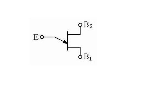 Symbol of UJTThe construction of the UJT is simple as it has one junction. The construction resembles diode. The difference in between the UJT and the diode is that it consists of three terminals in comparison with the diode. The higher resistance value is present at the bar that is of n-type. The maximum value for the resistance is formed in between the terminals of the base 1 and the emitter in comparison with the resistance value of the terminals base2 and the emitter. The reason for this is that the positioning of the emitter is nearer or closer to the base 2 rather than base 1. The above connections makes a basic circuit diagram of UJT.This transistor is operated by making the junction of the terminal in the forward biasing mode. The operation of this UJT is unique but it doesn’t amplify the signals but capable enough of handling and controlling the larger vale of the power applied in terms of AC. It also exhibits the resistance in terms of negative polarity. This makes the UJT to utilize it as an oscillator circuit. UJT CharacteristicsThe characteristics of the UJT are as followsIt requires very low amounts of the voltage to get triggered.It is capable of controlling the current pulse.It consists of the negative value of the resistance.The cost of this transistor is very low.
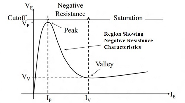 UJT Characteristics Curve As the current in the UJT tends to increase there can be evident drop in voltage value. Hence this transistor shows the negative characteristics of resistance. This paves the way to make the UJT to work as a relaxation oscillator. The basic functional unit of this oscillator consists of resistor and the capacitor with UJT as the active unit for the oscillator to perform operation. UJT Relaxation OscillatorUJT is a transistor with one junction. This possesses the resistance with negative characteristics. This makes the UJT to function as an oscillator. This is an oscillator with the basic resistor and capacitor. As it is good at switching and it takes minimum value of the nano seconds for switching the devices. The circuitry of the relaxation oscillator consists of the resistors and the capacitor. The resistors act as the limiters of the current. Initially when the voltage is applied the UJT is considered to be OFF. The capacitor tends to charge through the resistor present there that is R. This charging of the capacitor is exponential in nature.As the diode exceeds the minimum value the device starts conducting by making the emitter junction to be in forward biasing mode. Hence the transistor is considered to be ON. This makes the resistance value between the emitter and the Base 1 to decrease and the device enters in to the region of saturation that is fully conducting. The flow of current of the terminal emitter through the resistor that is R1 takes place.
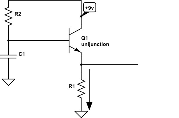 UJT as Relaxation OscillatorBy making the capacitor to get discharged because the resistor R1 is of low ohmic value. The discharge value of the capacitor is lesser than that of the charging value of the capacitor. Once the voltage across the capacitor tends to decrease more than that of the time of holding the device tends to get turned OFF. Based on the voltage applied as input dependent o it the device is managed to be turned ON or OFF.Difference between UJT and BJTThe basic differences between the UJT and the BJT are as follows. Uni junction Transistor (UJT) Bipolar Junction Transistor (BJT) 1. Only one junction is present in UJT. 1. It consists of two Junctions. It is a two junction transistor. 2. The conduction in this transistor is based on the flow of the majority of the carriers through it. 2. The conduction in this transistor is completely based on the flow of the both majority as well as the minority carriers through it. 3. It can be used as the voltage control device. 3. It can be categorized as the current control device. 4. UJT cannot be preferred for amplification. 4. BJT can be used as amplifiers. 5. UJTs are preferred for the switching applications. 5. Based on the operating regions it can be preferred for amplification as well as suitable for the switching of the devices. In this way the UJT and the BJTs are classified based on the basic operating differences.As the applied voltage decides the flow of current and thus making the device to get turn ON and OFF this makes the device as voltage control capable. As it is dependent only on the majority of the flow of carriers it is referred to as the uni junction device. It possesses very unique operating characteristics. It cannot support amplification but can provide good switching because it has nano seconds of the time in between the switching of the devices.Hence the UJT possesses the characteristics of the negative value of the resistance by making the device too use it in an oscillator. It can be used in various triggering circuits because of the operation is dependent on the triggering of the emitter. Over all UJT looks like JFET resembles like diode because of one junction in it but its way of operation is completely different. In this way UJT is defined with its own specifications. As it is a good switch but still it possesses unique characteristics in comparison with other transistors. Now can you describe the practical example of the UJT?
Leave a message
Message List
Comments Loading...
