
Products Category
- FM Transmitter
- 0-50w 50w-1000w 2kw-10kw 10kw+
- TV Transmitter
- 0-50w 50-1kw 2kw-10kw
- FM Antenna
- TV Antenna
- Antenna Accessory
- Cable Connector Power Splitter Dummy Load
- RF Transistor
- Power Supply
- Audio Equipments
- DTV Front End Equipment
- Link System
- STL system Microwave Link system
- FM Radio
- Power Meter
- Other Products
- Special for Coronavirus
Products Tags
Fmuser Sites
- es.fmuser.net
- it.fmuser.net
- fr.fmuser.net
- de.fmuser.net
- af.fmuser.net ->Afrikaans
- sq.fmuser.net ->Albanian
- ar.fmuser.net ->Arabic
- hy.fmuser.net ->Armenian
- az.fmuser.net ->Azerbaijani
- eu.fmuser.net ->Basque
- be.fmuser.net ->Belarusian
- bg.fmuser.net ->Bulgarian
- ca.fmuser.net ->Catalan
- zh-CN.fmuser.net ->Chinese (Simplified)
- zh-TW.fmuser.net ->Chinese (Traditional)
- hr.fmuser.net ->Croatian
- cs.fmuser.net ->Czech
- da.fmuser.net ->Danish
- nl.fmuser.net ->Dutch
- et.fmuser.net ->Estonian
- tl.fmuser.net ->Filipino
- fi.fmuser.net ->Finnish
- fr.fmuser.net ->French
- gl.fmuser.net ->Galician
- ka.fmuser.net ->Georgian
- de.fmuser.net ->German
- el.fmuser.net ->Greek
- ht.fmuser.net ->Haitian Creole
- iw.fmuser.net ->Hebrew
- hi.fmuser.net ->Hindi
- hu.fmuser.net ->Hungarian
- is.fmuser.net ->Icelandic
- id.fmuser.net ->Indonesian
- ga.fmuser.net ->Irish
- it.fmuser.net ->Italian
- ja.fmuser.net ->Japanese
- ko.fmuser.net ->Korean
- lv.fmuser.net ->Latvian
- lt.fmuser.net ->Lithuanian
- mk.fmuser.net ->Macedonian
- ms.fmuser.net ->Malay
- mt.fmuser.net ->Maltese
- no.fmuser.net ->Norwegian
- fa.fmuser.net ->Persian
- pl.fmuser.net ->Polish
- pt.fmuser.net ->Portuguese
- ro.fmuser.net ->Romanian
- ru.fmuser.net ->Russian
- sr.fmuser.net ->Serbian
- sk.fmuser.net ->Slovak
- sl.fmuser.net ->Slovenian
- es.fmuser.net ->Spanish
- sw.fmuser.net ->Swahili
- sv.fmuser.net ->Swedish
- th.fmuser.net ->Thai
- tr.fmuser.net ->Turkish
- uk.fmuser.net ->Ukrainian
- ur.fmuser.net ->Urdu
- vi.fmuser.net ->Vietnamese
- cy.fmuser.net ->Welsh
- yi.fmuser.net ->Yiddish
Transistor Working Basic
Date:2021/10/18 21:55:57 Hits:
 .
.

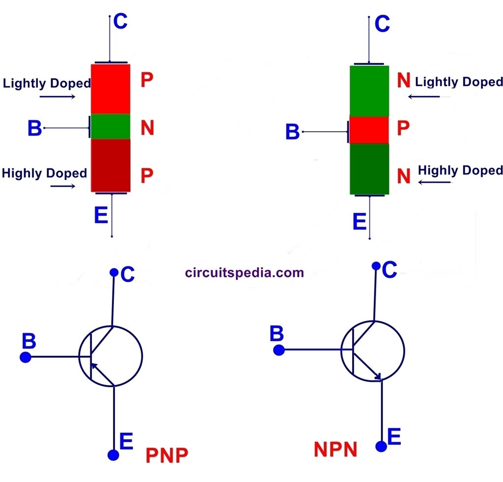
 Note – If use Relay in any circuit then a Diode (called as flyback diode) must connect with parallel of Relay input, This is essential for protection. Both with PNP and NPN transistor, Flyback diode is must in reverse bias.
The current supply between collector and emitter controlled by the supply signal of the Base terminal. If the signal at Base increase then also current conduction between emitter and collector increased. The base terminal of transistor works as the adjustable knob of any water tip/Bowl. That controls the amount of water passing through it.
The current conduction in a general transistor (NPN and PNP) is done by both polarities, negative supply as well as positive supply because of both minority and majority carrier. So this is called bipolar junction transistor (BJT).
Bipolar Junction Transistors operate within three different regions
Active Region – the transistor operates as an amplifier
Saturation – the transistor is “Fully-ON” operating as a switch and
Cut-off – the transistor is “Fully-OFF” operating as a switch
BJT IS CURRENT CONTROLLED
A BJT is a current controlled device because its output characteristics are determined by the input current.
if the output variations are due to input current variations, then this device is current controlled and if the output variations are due to input voltage variations, then the device is voltage controlled.
BJT is a current controlled device but MOSFET is a voltage controlled device.
In Electronics Transistor is widely used for the switching purpose.
In Logic gate designing in digital circuits transistors are also used.
Also read
How To Make A Blinking LED Circuit With 555
Light Activated Switch using Transistor
Automatic Night Lamp Using LDR
Delay ON Timer circuit using transistor
Note – If use Relay in any circuit then a Diode (called as flyback diode) must connect with parallel of Relay input, This is essential for protection. Both with PNP and NPN transistor, Flyback diode is must in reverse bias.
The current supply between collector and emitter controlled by the supply signal of the Base terminal. If the signal at Base increase then also current conduction between emitter and collector increased. The base terminal of transistor works as the adjustable knob of any water tip/Bowl. That controls the amount of water passing through it.
The current conduction in a general transistor (NPN and PNP) is done by both polarities, negative supply as well as positive supply because of both minority and majority carrier. So this is called bipolar junction transistor (BJT).
Bipolar Junction Transistors operate within three different regions
Active Region – the transistor operates as an amplifier
Saturation – the transistor is “Fully-ON” operating as a switch and
Cut-off – the transistor is “Fully-OFF” operating as a switch
BJT IS CURRENT CONTROLLED
A BJT is a current controlled device because its output characteristics are determined by the input current.
if the output variations are due to input current variations, then this device is current controlled and if the output variations are due to input voltage variations, then the device is voltage controlled.
BJT is a current controlled device but MOSFET is a voltage controlled device.
In Electronics Transistor is widely used for the switching purpose.
In Logic gate designing in digital circuits transistors are also used.
Also read
How To Make A Blinking LED Circuit With 555
Light Activated Switch using Transistor
Automatic Night Lamp Using LDR
Delay ON Timer circuit using transistor
Leave a message
Message List
Comments Loading...
