Products Category
- FM Transmitter
- 0-50w 50w-1000w 2kw-10kw 10kw+
- TV Transmitter
- 0-50w 50-1kw 2kw-10kw
- FM Antenna
- TV Antenna
- Antenna Accessory
- Cable Connector Power Splitter Dummy Load
- RF Transistor
- Power Supply
- Audio Equipments
- DTV Front End Equipment
- Link System
- STL system Microwave Link system
- FM Radio
- Power Meter
- Other Products
- Special for Coronavirus
Products Tags
Fmuser Sites
- es.fmuser.net
- it.fmuser.net
- fr.fmuser.net
- de.fmuser.net
- af.fmuser.net ->Afrikaans
- sq.fmuser.net ->Albanian
- ar.fmuser.net ->Arabic
- hy.fmuser.net ->Armenian
- az.fmuser.net ->Azerbaijani
- eu.fmuser.net ->Basque
- be.fmuser.net ->Belarusian
- bg.fmuser.net ->Bulgarian
- ca.fmuser.net ->Catalan
- zh-CN.fmuser.net ->Chinese (Simplified)
- zh-TW.fmuser.net ->Chinese (Traditional)
- hr.fmuser.net ->Croatian
- cs.fmuser.net ->Czech
- da.fmuser.net ->Danish
- nl.fmuser.net ->Dutch
- et.fmuser.net ->Estonian
- tl.fmuser.net ->Filipino
- fi.fmuser.net ->Finnish
- fr.fmuser.net ->French
- gl.fmuser.net ->Galician
- ka.fmuser.net ->Georgian
- de.fmuser.net ->German
- el.fmuser.net ->Greek
- ht.fmuser.net ->Haitian Creole
- iw.fmuser.net ->Hebrew
- hi.fmuser.net ->Hindi
- hu.fmuser.net ->Hungarian
- is.fmuser.net ->Icelandic
- id.fmuser.net ->Indonesian
- ga.fmuser.net ->Irish
- it.fmuser.net ->Italian
- ja.fmuser.net ->Japanese
- ko.fmuser.net ->Korean
- lv.fmuser.net ->Latvian
- lt.fmuser.net ->Lithuanian
- mk.fmuser.net ->Macedonian
- ms.fmuser.net ->Malay
- mt.fmuser.net ->Maltese
- no.fmuser.net ->Norwegian
- fa.fmuser.net ->Persian
- pl.fmuser.net ->Polish
- pt.fmuser.net ->Portuguese
- ro.fmuser.net ->Romanian
- ru.fmuser.net ->Russian
- sr.fmuser.net ->Serbian
- sk.fmuser.net ->Slovak
- sl.fmuser.net ->Slovenian
- es.fmuser.net ->Spanish
- sw.fmuser.net ->Swahili
- sv.fmuser.net ->Swedish
- th.fmuser.net ->Thai
- tr.fmuser.net ->Turkish
- uk.fmuser.net ->Ukrainian
- ur.fmuser.net ->Urdu
- vi.fmuser.net ->Vietnamese
- cy.fmuser.net ->Welsh
- yi.fmuser.net ->Yiddish
The Fundamentals of RF Mixers and RF Mixing
By Ian Poole
- RF mixers provide one of the key building blocks in RF design, enabling frequencies to be translated from one band to another by multiplying two signals together.
RF mixing is one of the key processes within RF technology and RF design. RF mixing enables signals to be converted to different frequencies and thereby allows the signals to be processed more effectively.
RF mixing basics
RF mixing is not like audio mixing where several signals are added together in a linear fashion to give several sounds together. Radio frequency, or RF mixing is a non-linear process that involves the instantaneous level of one signal affecting the level of the other at the output. This process involves the two signal levels multiplying together at any given instant in time and the output is a complex waveform consisting of the product of the two input signals.

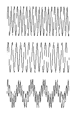
The result of two signals mixed together
In the diagram, the top two traces show the input signals to the RF mixer, and the bottom trace shows the output from the RF mixer. Looking at a plot or oscilloscope trace of the output it can be imagined that signals on different frequencies are produced, and this is in fact the case.
The RF mixing process
When added to a circuit diagram, an RF mixer is often denoted by a circle with a cross in it as shown below. As can be seen, there are the two inputs and one output as shown.

RF mixer mathematics
If the input waveforms are taken as:
V2 = B sin ( 2 pi f2 t)
Then it is necessary to use the trignometrical expression:
Applying this to the input waveforms, i.e. multiplying them together in the RF mixer, the output is then:
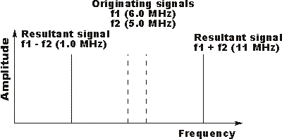
From this it can be seen that the two terms: (f1 - f2) and (f1 + f2) can be seen, and these represent the sum and difference frequencies that are seen on the traces above.
RF mixer summary


