
Products Category
- FM Transmitter
- 0-50w 50w-1000w 2kw-10kw 10kw+
- TV Transmitter
- 0-50w 50-1kw 2kw-10kw
- FM Antenna
- TV Antenna
- Antenna Accessory
- Cable Connector Power Splitter Dummy Load
- RF Transistor
- Power Supply
- Audio Equipments
- DTV Front End Equipment
- Link System
- STL system Microwave Link system
- FM Radio
- Power Meter
- Other Products
- Special for Coronavirus
Products Tags
Fmuser Sites
- es.fmuser.net
- it.fmuser.net
- fr.fmuser.net
- de.fmuser.net
- af.fmuser.net ->Afrikaans
- sq.fmuser.net ->Albanian
- ar.fmuser.net ->Arabic
- hy.fmuser.net ->Armenian
- az.fmuser.net ->Azerbaijani
- eu.fmuser.net ->Basque
- be.fmuser.net ->Belarusian
- bg.fmuser.net ->Bulgarian
- ca.fmuser.net ->Catalan
- zh-CN.fmuser.net ->Chinese (Simplified)
- zh-TW.fmuser.net ->Chinese (Traditional)
- hr.fmuser.net ->Croatian
- cs.fmuser.net ->Czech
- da.fmuser.net ->Danish
- nl.fmuser.net ->Dutch
- et.fmuser.net ->Estonian
- tl.fmuser.net ->Filipino
- fi.fmuser.net ->Finnish
- fr.fmuser.net ->French
- gl.fmuser.net ->Galician
- ka.fmuser.net ->Georgian
- de.fmuser.net ->German
- el.fmuser.net ->Greek
- ht.fmuser.net ->Haitian Creole
- iw.fmuser.net ->Hebrew
- hi.fmuser.net ->Hindi
- hu.fmuser.net ->Hungarian
- is.fmuser.net ->Icelandic
- id.fmuser.net ->Indonesian
- ga.fmuser.net ->Irish
- it.fmuser.net ->Italian
- ja.fmuser.net ->Japanese
- ko.fmuser.net ->Korean
- lv.fmuser.net ->Latvian
- lt.fmuser.net ->Lithuanian
- mk.fmuser.net ->Macedonian
- ms.fmuser.net ->Malay
- mt.fmuser.net ->Maltese
- no.fmuser.net ->Norwegian
- fa.fmuser.net ->Persian
- pl.fmuser.net ->Polish
- pt.fmuser.net ->Portuguese
- ro.fmuser.net ->Romanian
- ru.fmuser.net ->Russian
- sr.fmuser.net ->Serbian
- sk.fmuser.net ->Slovak
- sl.fmuser.net ->Slovenian
- es.fmuser.net ->Spanish
- sw.fmuser.net ->Swahili
- sv.fmuser.net ->Swedish
- th.fmuser.net ->Thai
- tr.fmuser.net ->Turkish
- uk.fmuser.net ->Ukrainian
- ur.fmuser.net ->Urdu
- vi.fmuser.net ->Vietnamese
- cy.fmuser.net ->Welsh
- yi.fmuser.net ->Yiddish
How to Make 5 Km Long Range FM Transmitter?
Here we are presenting a long range FM transmitter that can cover a reasonable distance of 5 kilometers / 3 miles and beyond with a one watt RF power with full circuit details, bill of material and testing procedure. With 12 volt DC it will deliver 1 watt RF power. With Yagi antenna, looking like early days of TV antenna with aluminum pipes at both at transmitter and receiver end looking each other at line of sight distance, the range can be up to 5 km / 3 miles.

This FM transmitter has 3 RF stages.
A (VFO) Variable frequency Oscillator (30 mw) ,A class C driver stage (150 mw) as buffer and
A class C final RF power amplifier (1 Watt )
Basically every FM Transmitter has to have a Voltage Controlled Oscillator (VCO) . This is a high frequency oscillator whose output frequency changes based on the voltage applied at a particular control point. This is a variable frequency oscillator (VFO).Q1 with is associated components form the VFO. The VFO output is fed to Q2. Q2 being a buffer does not load the VFO but amplifies the power only. This output is fed to the final RF power amplifier Q3, the output of which feeds the tuned circuit. Several capacitors C 4,8,9,10 are used on the supply rail for HF filtrations .If one feeds the VFO transistor Q1 directly with a microphone at its base it becomes a FM Transmitter circuit.
The Q2 pack has to be "TO 92-B" type(slightly bigger than BC547 pack) and not simple TO 92 which is slightly smaller in size ( same like BC547 pack). Moreover please note that the pin configurations are different for these 2 types. In case TO92 pack is used then increase the value of R7 to 56 ohms 1/2 watt failing which it shall burn. But this TO92 pack may affect the range
Q3 has to be 2N3866 with a heat sink for proper range. However 2N 2219 can be used that will but compromise the range drastically
Step 3: Testing
Initially use a simple 75CM single wire standing straight as antenna for getting a range of about 100-200 meters indoor. Similar length telescopic antenna is also OK for testing which will give only about 100-200 meters range . But never go longer than 79 CM antenna wire thinking that it will cover higher range. In fact if you do so the range will fall.
Frequency of the transmitter can be set with in 88 to 108 MHz FM band by adjusting the TR1 (Trimmer 1) of the VFO or by changing the spacing between the Coil L1.
NOTE: Don't try to test the unit in evening to night because at that time many powerful FM stations will be active. Test it only at day time. A few people have had trouble with this circuit if not soldered properly. The biggest problem is not knowing if it is even oscillating, since the frequency is outside the range of most simple oscilloscopes. One may require the use of an RF frequency counter which is very expensive. So, to know that it oscillates, and just have to find out at what frequency , the simplest way is to put a cell phone having FM radio ( or any FM radio) in search mode near your transmitter to hear some sound while you tap the microphone. Please note very near the transmitter will have several frequencies responding to the microphone and one will get confused. So go ,at least 30 meters away from the transmitter after initial test as above is verified. There the display gives only one frequency to which it gets best clear sound and all other frequencies giving hissing sound and that is the frequency the transmitter is operating. Adjust the trimmer TR1a very very very (about 1 degree) little clockwise or anticlockwise ,the transmission frequency will change .Then put the cell phone to search again and find the frequency. If it is very near a powerful transmitter you will not get the range. Change the frequency again to go towards 106 MHz where no commercial transmission usually takes place.
Transmission range is adjusted by TR2. For that use a multi meter in 250 mA DC current mode in series with the 12 volt supply and then adjust the trimmer TR2 while the current is maximum. Adjust the current to around 75 mA (at 12 Volt DC supplied by a good adaptor) or the peak current by trimmer 2 to say about 85 mA. From the peak while you turn clockwise current will fall or while you turn anti clockwise it will also fall. And that is the best position of TR2 for full power delivery to the antenna. Please note Q3, round metal body must be fully covered by the black heatsink supplied, without which it will get badly heated up and finally get burnt. In around 100mA at 12 volt it shall cover a good range and shall be warm but beyond that current though it may cover a longer range it shall get very badly heated up ,and is likely to fail.Initially try to touch the heatsink and feel the heat as warm only. If it gets heated up badly switch off and reduce the current.
Important Note:
(Don't use a metallic screw driver .You have to use a small piece non iron metallic object to work as a screwdriver - this will not alter the frequency while you take your hand near or away from the trimmer that usually happens in a metallic one).Copper or aluminum screw driver with insulated top is preferred.
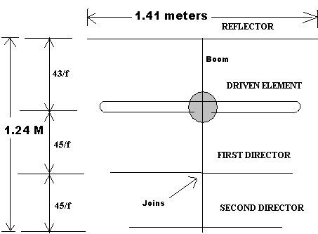
For Long Range use a Yagi antenna
The output is fed to a coaxial cable (generally used for cable TV ) which is nearly matched to the Yagi antenna (though 300 Ohms) impedance of 75 ohms by trimmer TR 2 of the tuned circuit for maximum power delivery to the load ie the Yagi / GP antenna. Transmitter should never be powered without the antenna (ie the load) in which case the total power forms a SWR standing wave ratio on the power transistor Q3 heating it up badly to result in failure.
Notes
1. It is advisable to engage any electronics technician for soldering if one has no prior professional experience in soldering and component identifying. Any excess heating more than 2 seconds may damage the component. Use only 25 watt soldering iron. Placing right value of resistor is most important. Read the colors carefully to ascertain its value. If a multimeter is available , then better measure it in ohms / Kohms range. It may not give exact value. Plus or minus 10% is acceptable. Reading disk ceramic capacitors need expertise. Place them correctly. Please refer the image.
2. Some components might have accumulated dirt on their legs by oxidation due to storage. Must clean them thoroughly to remove the dirt with a knife all around before soldering. The metal transistor as an example as seen in the packet. Better clean all the component legs even if they have no dirt on them.
3. If the trimmer pins are not going inside the holes try to slightly make the holes on the PCB bigger by some sharp pointed pin.
4. Mount the black heat sink on the metal transistor before mounting on the PCB.
5. Solder cut pcs of resistor legs to the microphone and solder them on to the PCB by proper polarity. The body is -ve.
6. Maintain the legs of transistors at least 5mm above the PCB and all resistor legs & coils on sleeping position as close to the PCB. Capacitors as usual standing but solder the legs as short as possible to the board.
7. The coils are super enameled coated. Don't be under the impression that they are copper. Must clean their ends only thoroughly to remove the enamel with a knife before soldering.
8. Must take a tapping from coil no 1, after 1 turn by scratching with a knife the enamel at a point and then use any cut piece copper wire of resistor (not iron wire) to solder there and connect the wire end to the hole on the PCB .
9. L3 and L4 must be at 90 degrees to each other.
10. Cleaning the dirt and rust on the legs as explained are very very important. All technicians know it. A beginner must understand this. Otherwise those components will never catch solder.
11. May use 9 volt battery by soldering the red to +ve and black to -ve. For using on 12 volt the DC socket has 3 pins. The center pin is 12v + and other 2 pins are for 12 volt -ve. Connect the same accordingly with small pcs of wire. Red + ,Black -ve to the DC socket.


Maybe you will like:
How to make a 15W FM transmitter for your own radio station?
How to make your own 4W FM Transmitter?
Long Range 25W FM Transmitter Kit


