Products Category
- FM Transmitter
- 0-50w 50w-1000w 2kw-10kw 10kw+
- TV Transmitter
- 0-50w 50-1kw 2kw-10kw
- FM Antenna
- TV Antenna
- Antenna Accessory
- Cable Connector Power Splitter Dummy Load
- RF Transistor
- Power Supply
- Audio Equipments
- DTV Front End Equipment
- Link System
- STL system Microwave Link system
- FM Radio
- Power Meter
- Other Products
- Special for Coronavirus
Products Tags
Fmuser Sites
- es.fmuser.net
- it.fmuser.net
- fr.fmuser.net
- de.fmuser.net
- af.fmuser.net ->Afrikaans
- sq.fmuser.net ->Albanian
- ar.fmuser.net ->Arabic
- hy.fmuser.net ->Armenian
- az.fmuser.net ->Azerbaijani
- eu.fmuser.net ->Basque
- be.fmuser.net ->Belarusian
- bg.fmuser.net ->Bulgarian
- ca.fmuser.net ->Catalan
- zh-CN.fmuser.net ->Chinese (Simplified)
- zh-TW.fmuser.net ->Chinese (Traditional)
- hr.fmuser.net ->Croatian
- cs.fmuser.net ->Czech
- da.fmuser.net ->Danish
- nl.fmuser.net ->Dutch
- et.fmuser.net ->Estonian
- tl.fmuser.net ->Filipino
- fi.fmuser.net ->Finnish
- fr.fmuser.net ->French
- gl.fmuser.net ->Galician
- ka.fmuser.net ->Georgian
- de.fmuser.net ->German
- el.fmuser.net ->Greek
- ht.fmuser.net ->Haitian Creole
- iw.fmuser.net ->Hebrew
- hi.fmuser.net ->Hindi
- hu.fmuser.net ->Hungarian
- is.fmuser.net ->Icelandic
- id.fmuser.net ->Indonesian
- ga.fmuser.net ->Irish
- it.fmuser.net ->Italian
- ja.fmuser.net ->Japanese
- ko.fmuser.net ->Korean
- lv.fmuser.net ->Latvian
- lt.fmuser.net ->Lithuanian
- mk.fmuser.net ->Macedonian
- ms.fmuser.net ->Malay
- mt.fmuser.net ->Maltese
- no.fmuser.net ->Norwegian
- fa.fmuser.net ->Persian
- pl.fmuser.net ->Polish
- pt.fmuser.net ->Portuguese
- ro.fmuser.net ->Romanian
- ru.fmuser.net ->Russian
- sr.fmuser.net ->Serbian
- sk.fmuser.net ->Slovak
- sl.fmuser.net ->Slovenian
- es.fmuser.net ->Spanish
- sw.fmuser.net ->Swahili
- sv.fmuser.net ->Swedish
- th.fmuser.net ->Thai
- tr.fmuser.net ->Turkish
- uk.fmuser.net ->Ukrainian
- ur.fmuser.net ->Urdu
- vi.fmuser.net ->Vietnamese
- cy.fmuser.net ->Welsh
- yi.fmuser.net ->Yiddish
RF Spectrum Analyzers Not Just for Consultants
February 29, 2016
Back in the 1960s, when I started working in radio broadcast engineering, an oscilloscope was my “eye” on what was happening with equipment. That tool served me well and is still in daily use in my service shop.
It’s true that fewer engineers use oscilloscopes now that we are in a plug’n’play world. However, they tell a story that cannot be read on a voltmeter or discerned with an ear. An RF spectrum analyzer was added to my tool arsenal 30 years ago as yet another problem solver.
Good friend and fellow Radio World writer Charles “Buc” Fitch said, “An oscilloscope is like a super visual voltmeter, while a spectrum analyzer is a bar graph of all the signal levels spread out on a radio dial.”
I say an analyzer is my eye on the RF spectrum, an indispensable tool.
Let me explain. Just because a transmitter has been tested at a factory doesn’t mean it will perform correctly in the field, especially in high RF environments.
Among the first things I look for are “mixing products” between transmitters on site. Transmitters from as far as 10 miles away can cause mixing in a transmitter, resulting in unwanted signals that do not comply with FCC rules. An example is a combined AM/FM site. The AM signal, say at 1000 kHz, gets into the FM exciter, causing unwanted signals (spurs) 1 MHz (1000 kHz) on either side of the FM signal. This usually happens when audio is fed to an active balanced composite input on the FM transmitter’s exciter. Double shielded cable or grounding the shield at the exciter input usually takes care of the problem.
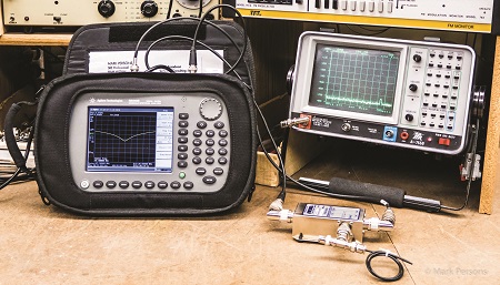
Fig. 1 An Agilent N9340B and an IFR A-7550 Spectrum Analyzers with Eagle RLB150X3 Return Loss Bridge on a service bench ready for action.
A spectrum analyzer will tell the story. Without one, you may not know there is a problem or how bad it is.
Fig. 1 shows my two spectrum analyzers on a service bench. Weighing in at just 12 pounds on the left is the Agilent, now Keysight, N9340B. On the right is my first analyzer, an IFR A7550. It dates back to the 1980s and weighs about 40 pounds. In the middle is a return loss bridge.
A spectrum analyzer, connected to a return loss bridge, is a great way to look at antenna Voltage Standing Wave Ratio. My favorite is the Eagle RLB150X3 return loss bridge, available for as little as $250. Yes, it is a poor man’s 5 to 1000 MHz network analyzer, but it tells almost everything I need to know about a transmitter load. Return loss bridges are three-port devices with an input from a spectrum analyzer tracking generator, a port for the unknown load, and an output to the spectrum analyzer’s input.
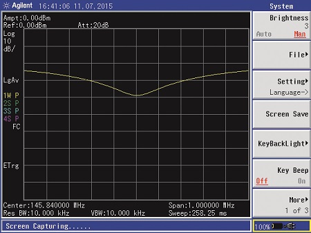
Using a return loss bridge, I can see a VSWR picture of what the load looks like at the frequency of interest and nearby frequencies. I might discover that an antenna is not on frequency, but off a bit. The display shows how far off and I can, in real time, see how antenna adjustments change the operating characteristics. Fig. 2 shows VSWR on one of my amateur radio antennas.
Return loss bridges are really four-port devices. The fourth port is usually an internal 50 ohm resistor, which is used as a reference to compare the unknown load to. Some bridges have a 75 ohm resistor for 75 ohm measurements. Signal from the tracking generator is an input to a “bridge” circuit. If the unknown load resistance matches the reference resistor, there is high loss through the bridge. Start by putting a short on the unknown port and read signal going back to the spectrum analyzer. That is your reference. Put an antenna or other load on the bridge and see how close it is to the reference at the frequency of interest and nearby frequencies. If the analyzer shows the unknown load is 20 dB down from the reference (20 dB return loss), that tells you the VSWR is 1.22:1. 30 dB is 1.07:1. There are charts for that on the Internet.
TROUBLESHOOTING
I remember troubleshooting a Continental FM transmitter that intermittently dropped to near zero RF output. A spectrum analyzer told the story. The exciter was moving to a new frequency, due to intermittent DIP switches in its exciter frequency synthesizer. The mystery was quickly solved with a spectrum analyzer.
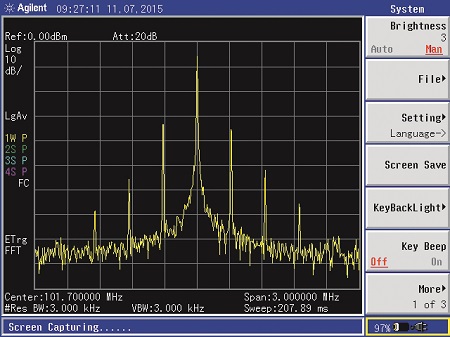
Fig. 3 Spurious radiation is plainly indicated from a faulty FM exciter under test.
An RF spectrum analyzer is a constant companion in my shop. I often see unwanted spurious radiation from FM exciters. Fig. 3 shows spurs spaced about every 300 kHz surrounding the exciter’s frequency. The usual cause is electrolytic capacitors in the exciter’s RF amplifier stage that have failed open. Capacitors at voltage regulators can cause the same symptom.
MAKE ADJUSTMENTS
You can use a spectrum analyzer with a tracking generator to adjust cavity filters. Fig. 4 shows a filter tuned to 161.64 mHz for use in protecting a remote pickup receiver from high local RF. Then there is Fig. 5 showing shorted quarter wave stub trap VSWR.
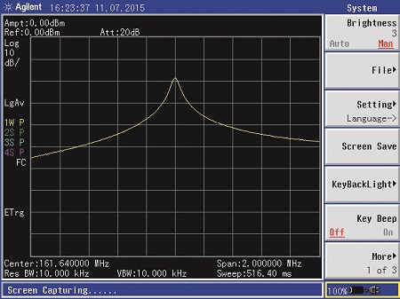
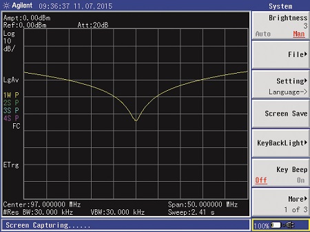
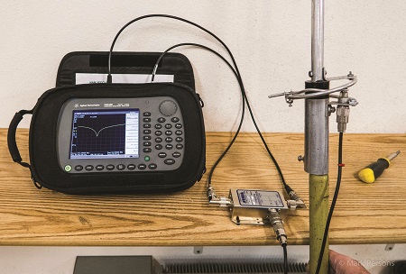
Fig. 6 A spectrum analyzer with return loss bridge measuring and tuning a remote pickup antenna for low reflected power.
Fig. 6 shows an analyzer with a return loss bridge looking at a Cushcraft Ringo 160 MHz remote pickup antenna. Antenna VSWR is plainly evident on the analyzer.
Having a spectrum analyzer and knowing how to use it are two different things. Many manufacturers have tutorials. You can learn from fellow engineers or better yet, Society of Broadcast Engineer members in your area. Become proficient at interpreting what you see on an analyzer screen. You might be amazed at what you find.
Not all RF spectrum analyzers are the same. Those in the $10,000+ range are usually self-contained. Less-expensive ones in the $1,000 range are often a box that connects to a computer. They let the computer do the number crunching and display. Best to get one with a tracking generator.
If your are purchasing an analyzer, I highly recommend one that has a 300 Hz or narrower resolution bandwidth filter so you can measure occupied bandwidth on AM stations accurately. Reading to 3 GHz or more is good too. You might need it when adjusting a satellite dish. How about 950 MHz STLs? They can go wild causing interference. An RF spectrum analyzer will tell the story.


