
Products Category
- FM Transmitter
- 0-50w 50w-1000w 2kw-10kw 10kw+
- TV Transmitter
- 0-50w 50-1kw 2kw-10kw
- FM Antenna
- TV Antenna
- Antenna Accessory
- Cable Connector Power Splitter Dummy Load
- RF Transistor
- Power Supply
- Audio Equipments
- DTV Front End Equipment
- Link System
- STL system Microwave Link system
- FM Radio
- Power Meter
- Other Products
- Special for Coronavirus
Products Tags
Fmuser Sites
- es.fmuser.net
- it.fmuser.net
- fr.fmuser.net
- de.fmuser.net
- af.fmuser.net ->Afrikaans
- sq.fmuser.net ->Albanian
- ar.fmuser.net ->Arabic
- hy.fmuser.net ->Armenian
- az.fmuser.net ->Azerbaijani
- eu.fmuser.net ->Basque
- be.fmuser.net ->Belarusian
- bg.fmuser.net ->Bulgarian
- ca.fmuser.net ->Catalan
- zh-CN.fmuser.net ->Chinese (Simplified)
- zh-TW.fmuser.net ->Chinese (Traditional)
- hr.fmuser.net ->Croatian
- cs.fmuser.net ->Czech
- da.fmuser.net ->Danish
- nl.fmuser.net ->Dutch
- et.fmuser.net ->Estonian
- tl.fmuser.net ->Filipino
- fi.fmuser.net ->Finnish
- fr.fmuser.net ->French
- gl.fmuser.net ->Galician
- ka.fmuser.net ->Georgian
- de.fmuser.net ->German
- el.fmuser.net ->Greek
- ht.fmuser.net ->Haitian Creole
- iw.fmuser.net ->Hebrew
- hi.fmuser.net ->Hindi
- hu.fmuser.net ->Hungarian
- is.fmuser.net ->Icelandic
- id.fmuser.net ->Indonesian
- ga.fmuser.net ->Irish
- it.fmuser.net ->Italian
- ja.fmuser.net ->Japanese
- ko.fmuser.net ->Korean
- lv.fmuser.net ->Latvian
- lt.fmuser.net ->Lithuanian
- mk.fmuser.net ->Macedonian
- ms.fmuser.net ->Malay
- mt.fmuser.net ->Maltese
- no.fmuser.net ->Norwegian
- fa.fmuser.net ->Persian
- pl.fmuser.net ->Polish
- pt.fmuser.net ->Portuguese
- ro.fmuser.net ->Romanian
- ru.fmuser.net ->Russian
- sr.fmuser.net ->Serbian
- sk.fmuser.net ->Slovak
- sl.fmuser.net ->Slovenian
- es.fmuser.net ->Spanish
- sw.fmuser.net ->Swahili
- sv.fmuser.net ->Swedish
- th.fmuser.net ->Thai
- tr.fmuser.net ->Turkish
- uk.fmuser.net ->Ukrainian
- ur.fmuser.net ->Urdu
- vi.fmuser.net ->Vietnamese
- cy.fmuser.net ->Welsh
- yi.fmuser.net ->Yiddish
What are Mutual impedance and interaction between antennas
Current circulating in one antenna generally induces a voltage across the feedpoint of nearby antennas or antenna elements. The mathematics presented below are useful in analyzing the electrical behaviour of antenna arrays, where the properties of the individual array elements (such as half wave dipoles) are already known. If those elements were widely separated and driven in a certain amplitude and phase, then each would act independently as that element is known to. However, because of the mutual interaction between their electric and magnetic fields due to proximity, the currents in each element are not simply a function of the applied voltage (according to its driving point impedance), but depend on the currents in the other nearby elements. Note that this now is a near field phenomenon which could not be properly accounted for using the Friis transmission equation for instance.
The elements' feedpoint currents and voltages can be related to each other using the concept of mutual impedance between every pair of antennas just as the mutual impedance describes the voltage induced in one inductor by a current through a nearby coil coupled to it through a mutual inductance M. The mutual impedance between two antennas is defined as:
where is the current flowing in antenna i and is the voltage induced at the open-circuited feedpoint of antenna j due to when all other currents ik are zero. The mutual impendances can be viewed as the elements of a symmetric square impedance matrix Z. Note that the diagonal elements, are simply the driving point impedances of each element.
Using this definition, the voltages present at the feedpoints of a set of coupled antennas can be expressed as the multiplication of the impedance matrix times the vector of currents. Written out as discrete equations, that means:
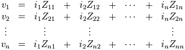
where:
 is the voltage at the terminals of antenna
 is the current flowing between the terminals of antenna
 is the driving point impedance of antenna
 is the mutual impedance between antennas
  and
and  .
.
As is the case for mutual inductances,

This is a consequence of Lorentz reciprocity. For an antenna element i not connected to anything (open circuited) one can write i_i=0. But for an element i which is short circuited, a current is generated across that short but no voltage is allowed, so the corresponding. This is the case, for instance, with the so-called parasitic elements of a Yagi-Uda antenna where the solid rod can be viewed as a dipole antenna shorted across its feedpoint. Parasitic elements are unpowered elements that absorb and reradiate RF energy according to the induced current calculated using such a system of equations.
With a particular geometry, it is possible for the mutual impedance between nearby antennas to be zero. This is the case, for instance, between the crossed dipoles used in the turnstile antenna.


