Products Category
- FM Transmitter
- 0-50w 50w-1000w 2kw-10kw 10kw+
- TV Transmitter
- 0-50w 50-1kw 2kw-10kw
- FM Antenna
- TV Antenna
- Antenna Accessory
- Cable Connector Power Splitter Dummy Load
- RF Transistor
- Power Supply
- Audio Equipments
- DTV Front End Equipment
- Link System
- STL system Microwave Link system
- FM Radio
- Power Meter
- Other Products
- Special for Coronavirus
Products Tags
Fmuser Sites
- es.fmuser.net
- it.fmuser.net
- fr.fmuser.net
- de.fmuser.net
- af.fmuser.net ->Afrikaans
- sq.fmuser.net ->Albanian
- ar.fmuser.net ->Arabic
- hy.fmuser.net ->Armenian
- az.fmuser.net ->Azerbaijani
- eu.fmuser.net ->Basque
- be.fmuser.net ->Belarusian
- bg.fmuser.net ->Bulgarian
- ca.fmuser.net ->Catalan
- zh-CN.fmuser.net ->Chinese (Simplified)
- zh-TW.fmuser.net ->Chinese (Traditional)
- hr.fmuser.net ->Croatian
- cs.fmuser.net ->Czech
- da.fmuser.net ->Danish
- nl.fmuser.net ->Dutch
- et.fmuser.net ->Estonian
- tl.fmuser.net ->Filipino
- fi.fmuser.net ->Finnish
- fr.fmuser.net ->French
- gl.fmuser.net ->Galician
- ka.fmuser.net ->Georgian
- de.fmuser.net ->German
- el.fmuser.net ->Greek
- ht.fmuser.net ->Haitian Creole
- iw.fmuser.net ->Hebrew
- hi.fmuser.net ->Hindi
- hu.fmuser.net ->Hungarian
- is.fmuser.net ->Icelandic
- id.fmuser.net ->Indonesian
- ga.fmuser.net ->Irish
- it.fmuser.net ->Italian
- ja.fmuser.net ->Japanese
- ko.fmuser.net ->Korean
- lv.fmuser.net ->Latvian
- lt.fmuser.net ->Lithuanian
- mk.fmuser.net ->Macedonian
- ms.fmuser.net ->Malay
- mt.fmuser.net ->Maltese
- no.fmuser.net ->Norwegian
- fa.fmuser.net ->Persian
- pl.fmuser.net ->Polish
- pt.fmuser.net ->Portuguese
- ro.fmuser.net ->Romanian
- ru.fmuser.net ->Russian
- sr.fmuser.net ->Serbian
- sk.fmuser.net ->Slovak
- sl.fmuser.net ->Slovenian
- es.fmuser.net ->Spanish
- sw.fmuser.net ->Swahili
- sv.fmuser.net ->Swedish
- th.fmuser.net ->Thai
- tr.fmuser.net ->Turkish
- uk.fmuser.net ->Ukrainian
- ur.fmuser.net ->Urdu
- vi.fmuser.net ->Vietnamese
- cy.fmuser.net ->Welsh
- yi.fmuser.net ->Yiddish
The Interpretation Of Car AM / FM Radio Circuit
How to design one that is both achieve cost control needs, but also to achieve high-quality audio enjoyment of broadcast audio products to meet the needs of this area to reduce costs and ease the design of the industry focus. To achieve cost-AM / FM car radio applications, we introduce a low-cost microcontroller MC9S08QG8, integrated radio chip TEF6621, low-cost and high-fidelity audio processing power output program and to streamline the hardware design of the circuit, while the description of the device selection, overall Construction of Ideas and hardware design details. The design can meet the low power, low cost, high performance, high quality requirements.
Specific hardware design
According to the previous considerations and overall build device selection, the paper finished AM / FM car radio specific design of the circuit shown in Figure 4. Wherein MC9S08QG8 microcontroller (MCU) Most pins have multiple functions, circuit design, that MC9S08QG8 as control core, implement the display, a variety of control tuning, audio sound amplifier output.
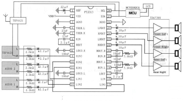
Here's AM / FM car radio applications schematic divided into three parts. The first part is MC9S08QG8 MCU basic connections required. The second part is TEF6621 tuner and antenna reception circuit, Part 3 is composed by the PT2313 and TDA7388 audio processing and power amplifier output circuit, Part 4 is 16x2 LCD and interactive potential of the encoder circuit.
Standard car battery voltage of 12/24 V, article design, the use of DC-DC voltage regulator circuit 9 V voltage output 1 and 1 5 V voltage, microcontrollers, and other low-voltage peripheral part is displayed as part of the 5 V power supply digital voltage, the tuner TEF6621 and audio chips PT2313 is 9 V power supply voltage, power amplifier TDA7388 car battery using a direct power supply. MCU clock circuit without an external crystal, comes directly using the internal MCU clock; the minimum hardware required to work the figure TEF6621 tuner, PT2313, TDA7388 and its peripheral circuit using the data sheet requirements. MCU and TEF6621 tuner, PT2313 connection in accordance with standard IIC connected, MCU as the host, TEF6621, PT2313 from the machine, by the SDA, SCL signal line base configuration and operation of two devices with different slave address achieve tuning and tuning features. The MCU 8K FLASH and 512 bytes of memory resources is sufficient for basic radio control, in addition, for further extensions in the present system, based on cause-chip resource constraints, Freescale also offers a pin-to-pin compatible The MC908QG16 / 32 and other low-cost upgrade program.
RS232 serial port to infrared communications circuit theory analysis
Infrared data transmission as a means of communication, can in many occasions, such as home appliances, infrared remote recreational facilities, water, electricity, gas and other energy metering automatic meter reading. Especially in the power electronics industry, using infrared technology to communicate more and more products, people can use infrared technology for short-range copy control products, it is very simple and convenient. Serial is a very common device communication protocol on the computer, based on most computers contain an RS 232 serial interface. The concept is very simple serial communication, serial bit (bit) of bytes sent and received. This article talked about communication uses three lines for: ground; transmitting; receiving. Since the serial communication is asynchronous, the port can send data on one line while receiving data in the other line.
Level Conversion
Since the level RS 232 signal level and single-chip serial signal inconsistent, must be level conversion between the two, often used to achieve MAX232 RS232 / TTL level conversion. MAX232 internal structure has three parts:
(1) The charge pump circuit. 1 to 6 by the pin and four capacitors built components.
(2) Data conversion channel. 7 to 14 by the composition of two data channels pins. RS 232 data from R1in, R2in input is converted into TTL / COMS after data output from R1out, R2out; TTL / COMS data from T1in, T2in input is converted to RS 232 data from T1out, T2out DB9 port to the computer.
RS232 serial port to infrared communications circuit theory analysis
Infrared emission part
When the infrared transmitter sends data, is to be sent as a series of binary data modulated burst signal is emitted, IR carrier frequency of 38 kHz square wave. IR carrier can use MCU internal PWM timer function implemented by peripheral hardware circuit can also be implemented here using 38 kHz crystal oscillator to generate a stable signal, using CD4069 NAND gate circuits through a series of square wave oscillation signal conversion, and after COMS data signal is superimposed on the converted level to implement the drive transistor is turned on, in order to achieve TSAL6200 infrared emitting diodes to convert electrical signals into a certain cycle frequency signals emitted infrared light, shown in Figure 2.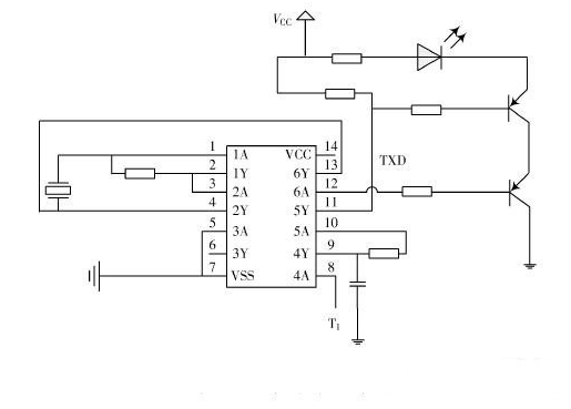
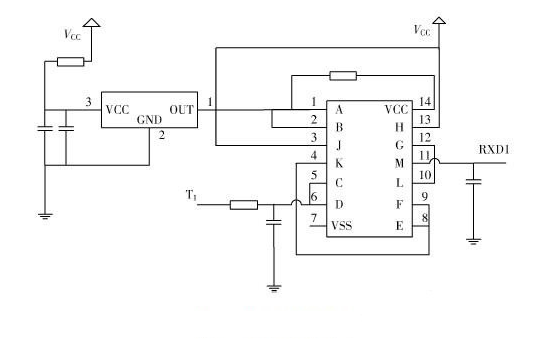
Infrared receiver using HS0038B infrared receiver, infrared receiver circuit principle is: When receiving the carrier signal of 38 kHz, HS0038B the receiver will output low, otherwise the output is high, thus the infrared light signal can be demodulated into a certain period continuous square wave signal, the microcontroller processing, it can recover the original data signal. HS0038B is able to receive the infrared signal receiving device miniaturization, it's epoxy package can as an infrared filter, so no plus infrared filter. The biggest advantage is in strong interference environment is also very stable output. Circuit design as shown, this article uses 3 CD4093 logic and non-gate chip and HS0038B the receiver circuit output data structures, while other groups use the chip for MAX232 output pin conversion level data from the lock, to avoid signal spontaneous self-closing .