Products Category
- FM Transmitter
- 0-50w 50w-1000w 2kw-10kw 10kw+
- TV Transmitter
- 0-50w 50-1kw 2kw-10kw
- FM Antenna
- TV Antenna
- Antenna Accessory
- Cable Connector Power Splitter Dummy Load
- RF Transistor
- Power Supply
- Audio Equipments
- DTV Front End Equipment
- Link System
- STL system Microwave Link system
- FM Radio
- Power Meter
- Other Products
- Special for Coronavirus
Products Tags
Fmuser Sites
- es.fmuser.net
- it.fmuser.net
- fr.fmuser.net
- de.fmuser.net
- af.fmuser.net ->Afrikaans
- sq.fmuser.net ->Albanian
- ar.fmuser.net ->Arabic
- hy.fmuser.net ->Armenian
- az.fmuser.net ->Azerbaijani
- eu.fmuser.net ->Basque
- be.fmuser.net ->Belarusian
- bg.fmuser.net ->Bulgarian
- ca.fmuser.net ->Catalan
- zh-CN.fmuser.net ->Chinese (Simplified)
- zh-TW.fmuser.net ->Chinese (Traditional)
- hr.fmuser.net ->Croatian
- cs.fmuser.net ->Czech
- da.fmuser.net ->Danish
- nl.fmuser.net ->Dutch
- et.fmuser.net ->Estonian
- tl.fmuser.net ->Filipino
- fi.fmuser.net ->Finnish
- fr.fmuser.net ->French
- gl.fmuser.net ->Galician
- ka.fmuser.net ->Georgian
- de.fmuser.net ->German
- el.fmuser.net ->Greek
- ht.fmuser.net ->Haitian Creole
- iw.fmuser.net ->Hebrew
- hi.fmuser.net ->Hindi
- hu.fmuser.net ->Hungarian
- is.fmuser.net ->Icelandic
- id.fmuser.net ->Indonesian
- ga.fmuser.net ->Irish
- it.fmuser.net ->Italian
- ja.fmuser.net ->Japanese
- ko.fmuser.net ->Korean
- lv.fmuser.net ->Latvian
- lt.fmuser.net ->Lithuanian
- mk.fmuser.net ->Macedonian
- ms.fmuser.net ->Malay
- mt.fmuser.net ->Maltese
- no.fmuser.net ->Norwegian
- fa.fmuser.net ->Persian
- pl.fmuser.net ->Polish
- pt.fmuser.net ->Portuguese
- ro.fmuser.net ->Romanian
- ru.fmuser.net ->Russian
- sr.fmuser.net ->Serbian
- sk.fmuser.net ->Slovak
- sl.fmuser.net ->Slovenian
- es.fmuser.net ->Spanish
- sw.fmuser.net ->Swahili
- sv.fmuser.net ->Swedish
- th.fmuser.net ->Thai
- tr.fmuser.net ->Turkish
- uk.fmuser.net ->Ukrainian
- ur.fmuser.net ->Urdu
- vi.fmuser.net ->Vietnamese
- cy.fmuser.net ->Welsh
- yi.fmuser.net ->Yiddish
PLL Phase Locked Loop Tutorial
PLL Phase Locked Loop Tutorial
-This phased locked loop tutorial looks at the PLL fundamentals and explains the basic concepts and the way the loop operates.PLL, Phase Locked Loop tutorial includes:
• PLL, phase locked loop tutorial
• VCO voltage controlled oscillator design
• Phase detector
• PLL loop filter design
• PLL loop gain
The phase locked loop, PLL can be used for a variety of radio frequency applications, from frequency synthesizers to clock recovery and FM demodulation.
As a result the phase locked loop is found in many items of radio frequency equipment including radio receivers, test equipment and other items of radio frequency electronics.
Phase locked loop development
The phase locked loop, PLL, was not used in early radio equipment because of the number of different stages required. However with the advent of radio frequency integrated circuits, the idea of phase locked loops, PLLs, became viable. Initially relatively low frequency PLLs became available, but as RF IC technology improved, so the frequency at which PLLs would operate rose, and high frequency versions became available.
Phase locked loop concepts - phase
The operation of a phase locked loop, PLL, is based around the idea of comparing the phase of two signals. This information about the error in phase or the phase difference between the two signals is then used to control the frequency of the loop.

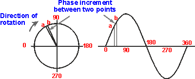
To look at the concept of phase difference, take the example of two signals. Although the two signals have the same frequency, the peaks and troughs do not occur in the same place. There is said to be a phase difference between the two signals. This phase difference is measured as the angle between them. It can be seen that it is the angle between the same point on the two waveforms. In this case a zero crossing point has been taken, but any point will suffice provided that it is the same on both.

When there two signals have different frequencies it is found that the phase difference between the two signals is always varying. The reason for this is that the time for each cycle is different and accordingly they are moving around the circle at different rates.
Phase locked loop basics
A phase locked loop, PLL, is basically of form of servo loop. Although a PLL performs its actions on a radio frequency signal, all the basic criteria for loop stability and other parameters are the same.
A basic phase locked loop, PLL, consists of three basic elements:
*Loop filter: This filter is used to filter the output from the phase comparator in the PLL. It is used to remove any components of the signals of which the phase is being compared from the VCO line. It also governs many of the characteristics of the loop and its stability.
*Voltage controlled oscillator (VCO): The voltage controlled oscillator is the circuit block that generates the output radio frequency signal. Its frequency can be controlled and swung over the operational frequency band for the loop.
Phase locked loop operation
The basic concept of the operation of the PLL is relatively simple, although the mathematical analysis and many elements of its operation can become more complicated
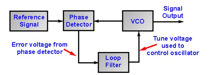
The basic phase locked loop is connected as shown in the diagram below. The reference signal and the signal from the voltage controlled oscillator are connected into the phase detector. The output from the phase detector is passed through the loop filter and then applied to the voltage controlled oscillator.

The Voltage Controlled Oscillator, VCO, within the PLL produces a signal which enters the phase detector. Here the phase of the signals from the VCO and the incoming reference signal are compared and a resulting difference or error voltage is produced. This corresponds to the phase difference between the two signals.
The error signal from the phase detector passes through a low pass filter which governs many of the properties of the loop and removes any high frequency elements on the signal. Once through the filter the error signal is applied to the control terminal of the VCO as its tuning voltage. The sense of any change in this voltage is such that it tries to reduce the phase difference and hence the frequency between the two signals. Initially the loop will be out of lock, and the error voltage will pull the frequency of the VCO towards that of the reference, until it cannot reduce the error any further and the loop is locked.
When the PLL, phase locked loop, is in lock a steady state error voltage is produced. By using an amplifier between the phase detector and the VCO, the actual error between the signals can be reduced to very small levels. However some voltage must always be present at the control terminal of the VCO as this is what puts onto the correct frequency.
The phase locked loop, PLL, is one of the most versatile building blocks in radio frequency electronics today. Whilst it was not widely used for many years, the advent of the IC meant that phase locked loop and synthesizer chips became widely available. This made them cheap to use and their advantages could be exploited to the full.


