Products Category
- FM Transmitter
- 0-50w 50w-1000w 2kw-10kw 10kw+
- TV Transmitter
- 0-50w 50-1kw 2kw-10kw
- FM Antenna
- TV Antenna
- Antenna Accessory
- Cable Connector Power Splitter Dummy Load
- RF Transistor
- Power Supply
- Audio Equipments
- DTV Front End Equipment
- Link System
- STL system Microwave Link system
- FM Radio
- Power Meter
- Other Products
- Special for Coronavirus
Products Tags
Fmuser Sites
- es.fmuser.net
- it.fmuser.net
- fr.fmuser.net
- de.fmuser.net
- af.fmuser.net ->Afrikaans
- sq.fmuser.net ->Albanian
- ar.fmuser.net ->Arabic
- hy.fmuser.net ->Armenian
- az.fmuser.net ->Azerbaijani
- eu.fmuser.net ->Basque
- be.fmuser.net ->Belarusian
- bg.fmuser.net ->Bulgarian
- ca.fmuser.net ->Catalan
- zh-CN.fmuser.net ->Chinese (Simplified)
- zh-TW.fmuser.net ->Chinese (Traditional)
- hr.fmuser.net ->Croatian
- cs.fmuser.net ->Czech
- da.fmuser.net ->Danish
- nl.fmuser.net ->Dutch
- et.fmuser.net ->Estonian
- tl.fmuser.net ->Filipino
- fi.fmuser.net ->Finnish
- fr.fmuser.net ->French
- gl.fmuser.net ->Galician
- ka.fmuser.net ->Georgian
- de.fmuser.net ->German
- el.fmuser.net ->Greek
- ht.fmuser.net ->Haitian Creole
- iw.fmuser.net ->Hebrew
- hi.fmuser.net ->Hindi
- hu.fmuser.net ->Hungarian
- is.fmuser.net ->Icelandic
- id.fmuser.net ->Indonesian
- ga.fmuser.net ->Irish
- it.fmuser.net ->Italian
- ja.fmuser.net ->Japanese
- ko.fmuser.net ->Korean
- lv.fmuser.net ->Latvian
- lt.fmuser.net ->Lithuanian
- mk.fmuser.net ->Macedonian
- ms.fmuser.net ->Malay
- mt.fmuser.net ->Maltese
- no.fmuser.net ->Norwegian
- fa.fmuser.net ->Persian
- pl.fmuser.net ->Polish
- pt.fmuser.net ->Portuguese
- ro.fmuser.net ->Romanian
- ru.fmuser.net ->Russian
- sr.fmuser.net ->Serbian
- sk.fmuser.net ->Slovak
- sl.fmuser.net ->Slovenian
- es.fmuser.net ->Spanish
- sw.fmuser.net ->Swahili
- sv.fmuser.net ->Swedish
- th.fmuser.net ->Thai
- tr.fmuser.net ->Turkish
- uk.fmuser.net ->Ukrainian
- ur.fmuser.net ->Urdu
- vi.fmuser.net ->Vietnamese
- cy.fmuser.net ->Welsh
- yi.fmuser.net ->Yiddish
What is the Dipole Antenna ?
In this section, the dipole antenna with a very thin radius is considered. The dipole antenna is similar to the short dipole except it is not required to be small compared to the wavelength (at the frequency the antenna is operating at).
For a dipole antenna of length L oriented along the z-axis and centered at z=0, the current flows in the z-direction with amplitude which closely follows the following function:
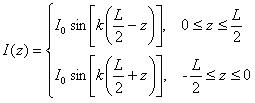
Note that this current is also oscillating in time sinusoidally at frequency f.
The current distributions for the quarter-wavelength (left) and full-wavelength (right)
dipole antennas are given in Figure 1. Note that the peak value of the current  is not reached along the
dipole unless the length is greater than half a wavelength.

Figure 1. Current distributions on finite-length dipole antennas.
Before examining the fields radiated by a dipole antenna, consider the input impedance of a dipole as a function of its length, plotted in Figure 2 below. Note that the input impedance is specified as Z=R + jX, where R is the resistance and X is the reactance.
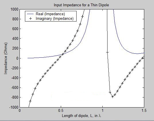
Figure 2. Input impedance as a function of the length (L) of a dipole antenna.
Note that for very small dipole antennas, the input impedance is capacitive, which means the impedance
is dominated by a negative reactance value (and a relatively small real impedance or resistance).
As the dipole gets larger, the input resistance increases, along with the reactance. At
slightly less than 0.5  the antenna has zero imaginary component to the impedance (reactance X=0), and the antenna
is said to be resonant.
If the dipole antenna's length becomes close to one wavelength, the input impedance becomes infinite. This wild change in input impedance can be understood by studying high frequency transmission line theory. As a simpler explanation, consider the one wavelength dipole shown in Figure 1. If a voltage is applied to the terminals on the right antenna in Figure 1, the current distribution will be as shown. Since the current at the terminals is zero, the input impedance (given by Z=V/I) will necessarily be infinite. Consequently, infinite impedance occurs whenever the dipole antenna is an integer multiple of a wavelength.
In the next section, we'll consider the radiation pattern of dipole antennas.
Radiation Patterns for Dipole Antennas
The far-fields from a dipole antenna of length L are given by:
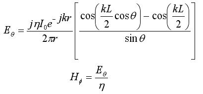
The normalized radiation patterns for dipole antennas of various lengths are shown in Figure 3.
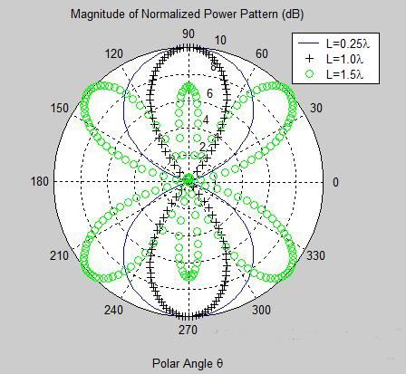
Figure 3. Normalized radiation patterns for dipole antennas of specified length.
The full-wavelength dipole antenna is more directional than the shorter quarter-wavelength dipole antenna. This is a typical result in antenna theory: it takes a larger antenna in general to increase directivity. However, the results are not always obvious. The 1.5-wavelength dipole pattern is also plotted in Figure 3. Note that this pattern is maximum at approximately +45 and -45 degrees.
The dipole antenna is symmetric when viewed azimuthally (around the long
axis of the dipole); as a result the radiation pattern is not a
function of
the azimuthal angle ![]() . Hence, the dipole antenna
is an example of an omnidirectional antenna. Further, the E-field only has one vector component and
consequently the fields are linearly polarized. When viewed in the x-y plane (for a dipole oriented along
the z-axis), the E-field is in the -y direction, and consequently the dipole antenna is vertically polarized.
. Hence, the dipole antenna
is an example of an omnidirectional antenna. Further, the E-field only has one vector component and
consequently the fields are linearly polarized. When viewed in the x-y plane (for a dipole oriented along
the z-axis), the E-field is in the -y direction, and consequently the dipole antenna is vertically polarized.
The 3D pattern for the 1-wavelength dipole antenna is shown in Figure 4. This pattern is similar to the pattern for the quarter- and half-wave dipole antenna.
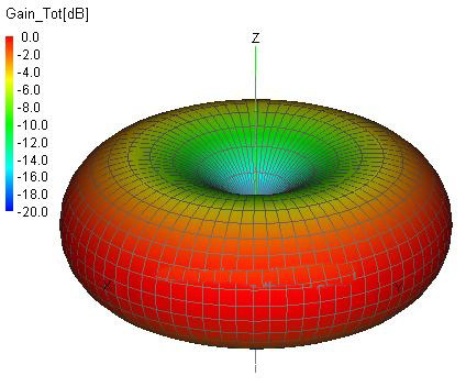
Figure 4. Normalized 3d radiation pattern for the 1-wavelength dipole antenna.
The 3D radiation pattern for the 1.5-wavelength dipole antenna is significantly different, and is shown in Figure 5.

Figure 5. Normalized 3d radiation pattern for the 1.5-wavelength dipole antenna.
The (peak) directivity of the dipole antenna varies as shown in Figure 6.
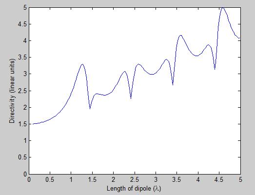
Figure 6. Dipole Antenna directivity as a function of dipole length.
Figure 6 indicates that up until approximately L=1.25  the directivity increases with length. However, for longer lengths the directivity has
an upward trend but is no longer monotonic.


