
Products Category
- FM Transmitter
- 0-50w 50w-1000w 2kw-10kw 10kw+
- TV Transmitter
- 0-50w 50-1kw 2kw-10kw
- FM Antenna
- TV Antenna
- Antenna Accessory
- Cable Connector Power Splitter Dummy Load
- RF Transistor
- Power Supply
- Audio Equipments
- DTV Front End Equipment
- Link System
- STL system Microwave Link system
- FM Radio
- Power Meter
- Other Products
- Special for Coronavirus
Products Tags
Fmuser Sites
- es.fmuser.net
- it.fmuser.net
- fr.fmuser.net
- de.fmuser.net
- af.fmuser.net ->Afrikaans
- sq.fmuser.net ->Albanian
- ar.fmuser.net ->Arabic
- hy.fmuser.net ->Armenian
- az.fmuser.net ->Azerbaijani
- eu.fmuser.net ->Basque
- be.fmuser.net ->Belarusian
- bg.fmuser.net ->Bulgarian
- ca.fmuser.net ->Catalan
- zh-CN.fmuser.net ->Chinese (Simplified)
- zh-TW.fmuser.net ->Chinese (Traditional)
- hr.fmuser.net ->Croatian
- cs.fmuser.net ->Czech
- da.fmuser.net ->Danish
- nl.fmuser.net ->Dutch
- et.fmuser.net ->Estonian
- tl.fmuser.net ->Filipino
- fi.fmuser.net ->Finnish
- fr.fmuser.net ->French
- gl.fmuser.net ->Galician
- ka.fmuser.net ->Georgian
- de.fmuser.net ->German
- el.fmuser.net ->Greek
- ht.fmuser.net ->Haitian Creole
- iw.fmuser.net ->Hebrew
- hi.fmuser.net ->Hindi
- hu.fmuser.net ->Hungarian
- is.fmuser.net ->Icelandic
- id.fmuser.net ->Indonesian
- ga.fmuser.net ->Irish
- it.fmuser.net ->Italian
- ja.fmuser.net ->Japanese
- ko.fmuser.net ->Korean
- lv.fmuser.net ->Latvian
- lt.fmuser.net ->Lithuanian
- mk.fmuser.net ->Macedonian
- ms.fmuser.net ->Malay
- mt.fmuser.net ->Maltese
- no.fmuser.net ->Norwegian
- fa.fmuser.net ->Persian
- pl.fmuser.net ->Polish
- pt.fmuser.net ->Portuguese
- ro.fmuser.net ->Romanian
- ru.fmuser.net ->Russian
- sr.fmuser.net ->Serbian
- sk.fmuser.net ->Slovak
- sl.fmuser.net ->Slovenian
- es.fmuser.net ->Spanish
- sw.fmuser.net ->Swahili
- sv.fmuser.net ->Swedish
- th.fmuser.net ->Thai
- tr.fmuser.net ->Turkish
- uk.fmuser.net ->Ukrainian
- ur.fmuser.net ->Urdu
- vi.fmuser.net ->Vietnamese
- cy.fmuser.net ->Welsh
- yi.fmuser.net ->Yiddish
What is the definition of voltage standing wave ratio?
SWR is, thus, the ratio between transmitted and reflected waves. A high SWR indicates poor transmission-line efficiency and reflected energy, which can damage the transmitter and decrease transmitter efficiency. Since SWR commonly refers to the voltage ratio, it is usually known as voltage standing wave ratio (VSWR).
VSWR and System Efficiency
In an ideal system 100% of the energy is transmitted from the power stages to the load. This requires an exact match between the source impedance, i.e., the characteristic impedance of the transmission line and all its connectors, and the load's impedance. The signal's AC voltage will be the same from end to end since it passes through without interference.
In real systems, however, mismatched impedances cause some of the power to be reflected back toward the source (like an echo). Reflections cause constructive and destructive interference, leading to peaks and valleys in the voltage at various times and distances along the line. VSWR measures these voltage variances. It is the ratio of the highest voltage anywhere along the transmission line to the lowest voltage.
Reflected Energy
When a transmitted wave hits a boundary such as the one between the lossless transmission line and load (Figure 1), some energy will be transmitted to the load and some will be reflected. The reflection coefficient relates the incoming and reflected waves as:
Γ = V-/V+(Eq1.)
Where V- is the reflected wave and V+ is the incoming wave. VSWR is related to the magnitude of the voltage reflection coefficient (Γ) by:
VSWR = (1 + |Γ|)/(1 – |Γ|)(Eq2.)
VSWR can be measured directly with an SWR meter. An RF test instrument such as a vector network analyzer (VNA) can be used to measure the reflection coefficients of the input port (S11) and the output port (S22). S11 and S22 are equivalent to Γ at the input and output port, respectively. The VNAs with math modes can also directly calculate and display the resulting VSWR value.
The return loss at the input and output ports can be calculated from the reflection coefficient, S11 or S22, as follows:
RLIN = 20log10|S11| dB(Eq3.)
RLOUT = 20log10|S22| dB(Eq4.)
The reflection coefficient is calculated from the characteristic impedance of the transmission line and the load impedance as follows:
Γ = (ZL - ZO)/(ZL + ZO)(Eq5.)
Where ZL is the load impedance and ZO is the characteristic impedance of the transmission line .
VSWR can also be expressed in terms of ZL and ZO. Substituting Equation 5 into Equation 2, we obtain:
VSWR = [1 + |(ZL - ZO)/(ZL + ZO)|]/[1 - |(ZL - ZO)/(ZL + ZO)|] = (ZL + ZO + |ZL - ZO|)/(ZL + ZO - |ZL - ZO|)
For ZL > ZO, |ZL - ZO| = ZL - ZO
Therefore:
VSWR = (ZL + ZO + ZL - ZO)/(ZL + ZO - ZL + ZO) = ZL/ZO. (Eq6.)
For ZL < ZO, |ZL - ZO| = ZO - ZL
Therefore:
VSWR = (ZL + ZO + ZO - ZL)/(ZL + ZO - ZO + ZL) = ZO/ZL.(Eq7.)
We noted above that VSWR is a specification given in ratio form relative to 1, as an example 1.5:1. There are two special cases of VSWR, ∞:1 and 1:1. A ratio of infinity to one occurs when the load is an open circuit. A ratio of 1:1 occurs when the load is perfectly matched to the transmission-line characteristic impedance.
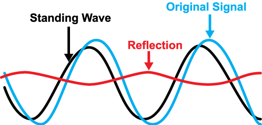
VSWR is defined from the standing wave that arises on the transmission line itself by:
VSWR = |VMAX|/|VMIN|(Eq8.)
Where VMAX is the maximum amplitude and VMIN is the minimum amplitude of the standing wave. With two super-imposed waves, the maximum occurs with constructive interference between the incoming and reflected waves. Thus:
VMAX = V+ + V-(Eq9.)
For maximum constructive interference. The minimum amplitude occurs with deconstructive interference, or:
VMIN = V+ - V-(Eq10.)
Substituting Equations 9 and 10 into Equation 8 yields
VSWR = |VMAX|/|VMIN| = (V+ + V-)/(V+ - V-)(Eq11.)
Substitute Equation 1 into Equation 11, we obtain:
VSWR = V+(1 + |Γ|)/(V+(1 - |Γ|) = (1 + |Γ|)/(1 – |Γ|)(Eq12.)
The MAX2016 is a dual logarithmic detector/controller used to monitor the VSWR/return loss of an antenna, when it is paired with a circulator and attenuator. The MAX2016 outputs the difference between the two power detectors.
The MAX2016 combined with the MAX5402 digital potentiometer and MAX1116/MAX1117 ADC forms a complete VSWR monitoring system . The digital potentiometer acts as a voltage-divider by using the MAX2016's reference voltage output. The internal reference voltage can typically source 2mA of current. This voltage sets the threshold voltage for the internal comparator (pin CSETL). An alarm can be generated when the output voltage crosses the threshold (pin COUTL). The MAX1116 ADC requires a 2.7V to 3.6V supply, while the MAX1117 ADC requires 4.5V to 5.5V. The ADC can also use an external reference voltage, provided by the MAX2016. The ADC paired with the microcontroller allows for constant monitoring of the antenna's VSWR.
Summary
In review, this tutorial describes SWR or VSWR as a way to measure transmission line imperfections and efficiency. VSWR is related to the reflection coefficient. A higher ratio depicts a larger mismatch, while 1:1 ratio is perfectly matched. This match or mismatch arises from the standing wave's maximum and minimum amplitude. SWR is related to the ratio between transmitted and reflected energy. The MAX2016 is shown as an example of how to create a system to monitor antenna VSWR.
You may also like:
What is VSWR: Voltage Standing Wave Ratio
