
Products Category
- FM Transmitter
- 0-50w 50w-1000w 2kw-10kw 10kw+
- TV Transmitter
- 0-50w 50-1kw 2kw-10kw
- FM Antenna
- TV Antenna
- Antenna Accessory
- Cable Connector Power Splitter Dummy Load
- RF Transistor
- Power Supply
- Audio Equipments
- DTV Front End Equipment
- Link System
- STL system Microwave Link system
- FM Radio
- Power Meter
- Other Products
- Special for Coronavirus
Products Tags
Fmuser Sites
- es.fmuser.net
- it.fmuser.net
- fr.fmuser.net
- de.fmuser.net
- af.fmuser.net ->Afrikaans
- sq.fmuser.net ->Albanian
- ar.fmuser.net ->Arabic
- hy.fmuser.net ->Armenian
- az.fmuser.net ->Azerbaijani
- eu.fmuser.net ->Basque
- be.fmuser.net ->Belarusian
- bg.fmuser.net ->Bulgarian
- ca.fmuser.net ->Catalan
- zh-CN.fmuser.net ->Chinese (Simplified)
- zh-TW.fmuser.net ->Chinese (Traditional)
- hr.fmuser.net ->Croatian
- cs.fmuser.net ->Czech
- da.fmuser.net ->Danish
- nl.fmuser.net ->Dutch
- et.fmuser.net ->Estonian
- tl.fmuser.net ->Filipino
- fi.fmuser.net ->Finnish
- fr.fmuser.net ->French
- gl.fmuser.net ->Galician
- ka.fmuser.net ->Georgian
- de.fmuser.net ->German
- el.fmuser.net ->Greek
- ht.fmuser.net ->Haitian Creole
- iw.fmuser.net ->Hebrew
- hi.fmuser.net ->Hindi
- hu.fmuser.net ->Hungarian
- is.fmuser.net ->Icelandic
- id.fmuser.net ->Indonesian
- ga.fmuser.net ->Irish
- it.fmuser.net ->Italian
- ja.fmuser.net ->Japanese
- ko.fmuser.net ->Korean
- lv.fmuser.net ->Latvian
- lt.fmuser.net ->Lithuanian
- mk.fmuser.net ->Macedonian
- ms.fmuser.net ->Malay
- mt.fmuser.net ->Maltese
- no.fmuser.net ->Norwegian
- fa.fmuser.net ->Persian
- pl.fmuser.net ->Polish
- pt.fmuser.net ->Portuguese
- ro.fmuser.net ->Romanian
- ru.fmuser.net ->Russian
- sr.fmuser.net ->Serbian
- sk.fmuser.net ->Slovak
- sl.fmuser.net ->Slovenian
- es.fmuser.net ->Spanish
- sw.fmuser.net ->Swahili
- sv.fmuser.net ->Swedish
- th.fmuser.net ->Thai
- tr.fmuser.net ->Turkish
- uk.fmuser.net ->Ukrainian
- ur.fmuser.net ->Urdu
- vi.fmuser.net ->Vietnamese
- cy.fmuser.net ->Welsh
- yi.fmuser.net ->Yiddish
How To Build An FM transmitter Circuit Its Working and Applications
The FM transmitter is a single transistor circuit. In the telecommunication, the frequency modulation (FM) transfers the information by varying the frequency of carrier wave according to the message signal. Generally, the FM transmitter uses VHF radio frequencies of 87.5 to 108.0 MHz to transmit & receive the FM signal. This transmitter accomplishes the most excellent range with less power. The performance and working of the wireless audio transmitter circuit is depends on the induction coil & variable capacitor. This article will explain about the working of the FM transmitter circuit with its applications.
What is an FM Transmitter?
The FM transmitter is a low power transmitter and it uses FM waves for transmitting the sound, this transmitter transmits the audio signals through the carrier wave by the difference of frequency. The carrier wave frequency is equivalent to the audio signal of the amplitude and the FM transmitter produce VHF band of 88 to 108MHZ.
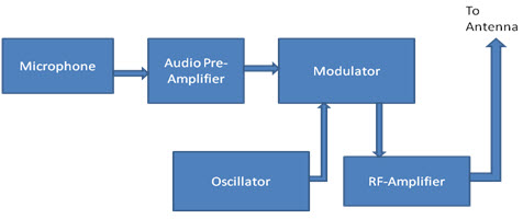
Block Diagram of FM Transmitter
The following image shows the block diagram of the FM transmitter and the required components of the FM transmitter are; microphone, audio pre amplifier, modulator, oscillator, RF- amplifier and antenna. There are two frequencies in the FM signal, first one is carrier frequency and the other one is audio frequency. The audio frequency is used to modulate the carrier frequency. The FM signal is obtained by differing the carrier frequency by allowing the AF. The FM transistor consists of oscillator to produce the RF signal.
The following circuit diagram shows the FM transmitter circuit and the required electrical and electronic components for this circuit is the power supply of 9V, resistor, capacitor, trimmer capacitor, inductor, mic, transmitter, and antenna. Let us consider the microphone to understand the sound signals and inside the mic there is a presence of capacitive sensor. It produces according to the vibration to the change of air pressure and the AC signal.
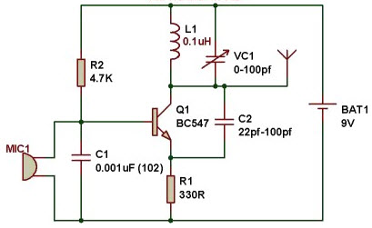
The formation of the oscillating tank circuit can be done through the transistor by using the inductor and variable capacitor. The transistor used in this circuit is an NPN transistor used for general purpose amplification. If the current is passed at the inductor L1 and variable capacitor then the tank circuit will oscillate at the resonant carrier frequency of the FM modulation. The negative feedback will be the capacitor C2 to the oscillating tank circuit.
To generate the radio frequency carrier waves the FM transmitter circuit requires an oscillator. The tank circuit is derived from the LC circuit to store the energy for oscillations. The input audio signal from the mic penetrated to the base of the transistor, which modulates the LC tank circuit carrier frequency in FM format. The variable capacitor is used to change the resonant frequency for fine modification to the FM frequency band. The modulated signal from the antenna is radiated as radio waves at the FM frequency band and the antenna is nothing but copper wire of 20cm long and 24 gauge. In this circuit the length of the antenna should be significant and here you can use the 25-27 inches long copper wire of the antenna.
Application of Fm Transmitter
1. The FM transmitters are used in the homes like sound systems in halls to fill the sound with the audio source.
2. These are also used in the cars and fitness centers.
3. The correctional facilities have used in the FM transmitters to reduce the prison noise in common areas.
Advantages of the FM Transmitters
1. The FM transmitters are easy to use and the price is low
2. The efficiency of the transmitter is very high
3. It has a large operating range
4. This transmitter will reject the noise signal from an amplitude variation.
Disadvantages of the FM Transmitter
1. In the FM transmitter the huge wider channel is required.
2. The FM transmitter and receiver will tend to be more complex.
3. Due to some interference there is poor quality in the received signals
