
Products Category
- FM Transmitter
- 0-50w 50w-1000w 2kw-10kw 10kw+
- TV Transmitter
- 0-50w 50-1kw 2kw-10kw
- FM Antenna
- TV Antenna
- Antenna Accessory
- Cable Connector Power Splitter Dummy Load
- RF Transistor
- Power Supply
- Audio Equipments
- DTV Front End Equipment
- Link System
- STL system Microwave Link system
- FM Radio
- Power Meter
- Other Products
- Special for Coronavirus
Products Tags
Fmuser Sites
- es.fmuser.net
- it.fmuser.net
- fr.fmuser.net
- de.fmuser.net
- af.fmuser.net ->Afrikaans
- sq.fmuser.net ->Albanian
- ar.fmuser.net ->Arabic
- hy.fmuser.net ->Armenian
- az.fmuser.net ->Azerbaijani
- eu.fmuser.net ->Basque
- be.fmuser.net ->Belarusian
- bg.fmuser.net ->Bulgarian
- ca.fmuser.net ->Catalan
- zh-CN.fmuser.net ->Chinese (Simplified)
- zh-TW.fmuser.net ->Chinese (Traditional)
- hr.fmuser.net ->Croatian
- cs.fmuser.net ->Czech
- da.fmuser.net ->Danish
- nl.fmuser.net ->Dutch
- et.fmuser.net ->Estonian
- tl.fmuser.net ->Filipino
- fi.fmuser.net ->Finnish
- fr.fmuser.net ->French
- gl.fmuser.net ->Galician
- ka.fmuser.net ->Georgian
- de.fmuser.net ->German
- el.fmuser.net ->Greek
- ht.fmuser.net ->Haitian Creole
- iw.fmuser.net ->Hebrew
- hi.fmuser.net ->Hindi
- hu.fmuser.net ->Hungarian
- is.fmuser.net ->Icelandic
- id.fmuser.net ->Indonesian
- ga.fmuser.net ->Irish
- it.fmuser.net ->Italian
- ja.fmuser.net ->Japanese
- ko.fmuser.net ->Korean
- lv.fmuser.net ->Latvian
- lt.fmuser.net ->Lithuanian
- mk.fmuser.net ->Macedonian
- ms.fmuser.net ->Malay
- mt.fmuser.net ->Maltese
- no.fmuser.net ->Norwegian
- fa.fmuser.net ->Persian
- pl.fmuser.net ->Polish
- pt.fmuser.net ->Portuguese
- ro.fmuser.net ->Romanian
- ru.fmuser.net ->Russian
- sr.fmuser.net ->Serbian
- sk.fmuser.net ->Slovak
- sl.fmuser.net ->Slovenian
- es.fmuser.net ->Spanish
- sw.fmuser.net ->Swahili
- sv.fmuser.net ->Swedish
- th.fmuser.net ->Thai
- tr.fmuser.net ->Turkish
- uk.fmuser.net ->Ukrainian
- ur.fmuser.net ->Urdu
- vi.fmuser.net ->Vietnamese
- cy.fmuser.net ->Welsh
- yi.fmuser.net ->Yiddish
How to Build a Simple Transistor Tester and its Working?
Transistors are tested with their pin layout and their types are observed. Designing the test circuit on a breadboard becomes inconvenient. So we will design simple which will be uncomplicated circuit that permits to test transistors.
In general, a transistor tester is used in microprocessor based expensive apparatus and boasts a luxurious indication of transistor terminals using alphabets b, e, and c. Transistor tester is an instrument which is used to test the electrical behavior of a transistor or diode. Multimeters or ohmmeters are suitable for both PNP and NPN transistor testing.
Types of Transistor Tester
Transistor tester is a type of instrument used to test the electrical behavior of transistors. There are three types of transistor testers each performing an exclusive operation:
>Quick Check in Circuit Checker
>Service Type Tester
>Laboratory Standard Tester
Quick Check in Circuit Checker
Quick check in circuit checker transistor tester is used to check whether a transistor is performing properly in a circuit or not. This type of transistor tester specifies to a technician whether a transistor is still operative or dead. The advantage of using this tester is such that among all the components in the circuit only transistor is not removed.
Service Type Transistor Tester
This type of transistor tester usually performs three types of tests: Forward current gain, base to collector leakage current with open emitter, and short circuits from collector to base and emitter.
Laboratory Standard Tester
A Laboratory Standard Tester is used to measure a transistor’s parameter at various operating conditions. The readings measured by this tester are accurate, and among the important characteristics measured are input resistance Rin, common base and common emitter.
Transistor Tester Procedure
The DMM or digital multimeter is one of the most common and useful items of test equipment. It is used to test the base to the emitter and base to collector PN junction of a BJT.
Procedure of a Transistor Tester Using a Digital Multimeter
A digital multimeter is used to test the base to the emitter and base to the collector PN junction of the BJT. By using this test, you can also identify the polarity of an unknown device. PNP and NPN transistor can be checked using the digital multimeter.
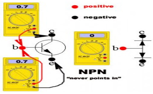
The digital multimeter consists of two leads: black and red. Connect the red (positive) lead to the base terminal of the PNP transistor, and the black (negative) lead to the emitter or the base terminal of the transistor. The voltage of a healthy transistor should be 0.7V, and the measurement across the emitter collector should read 0.0V. If the measured voltage is around 1.8V, then the transistor will be dead.
Similarly, connect the black lead (negative) to the base terminal of the NPN transistor, and red lead (positive) to the emitter or the collector terminal of the transistor. The voltage of a healthy transistor should be 0.7V, and the measurement across the emitter collector should read 0.0V. If the measured voltage is around 1.8V, then the transistor will be dead.
Transistor Tester Circuit
This transistor tester circuit that uses 555 timer IC is fit for testing both PNP and NPN transistors. This circuit is simple as compared to other transistor testers, and therefore, is useful for technicians as well as students. It can be easily built on a general purpose PCB. To develop this circuit, basic electronic components like resistors, diodes, LEDs and NE5555 are used. By using this circuit, different faults can be checked –like to know whether the condition of a transistor is good or not, and opened or shorted, and so on. NE 555 Timer IC is a multivibrator that works in three modes: astable, monostable and bistable. Also, this circuit can work through a battery for a long duration.
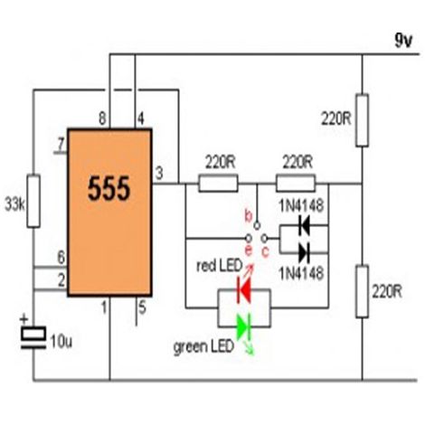
The working of this transistor tester circuit is such that it operates at 2Hz of frequency. The output pins 3 makes the transistor tester circuit with a positive voltage, and then with a non-zero voltage. At the other end of this circuit, a voltage divider is connected to the midpoint at approximate 4.5V, and the result will be like this.
When no transistor is connected to the tester, the green and red LEDs flash alternately. When the transistor is placed on the test lead, both the LEDs blink. If only one LED blinks, the condition of the transistor will be OK. If the voltage is only in one direction, it will produce short across the LED pair. If none of the LED flashes, the transistor will be shorted – and, if both the LEDs flash – the transistor will be open.
Transistor testers have essential switches and controls for making proper current, voltage, and signal settings. In addition, these transistor testers are designed to check the solid-state diodes. There are also preferred testers for checking high transistor and rectifiers.
If you want to buy Transistor, please click the link below:
http://fmuser.net/search.asp?page=1&keys=Transistor&searchtype=
